Startup
56
OAU-SVX006E-EN
surrounding buildings or prevailing winds cause
recirculation, a flue extension may be required to
prevent recirculation. Contact manufacturer prior
to making any flue adjustments.
•
Reduced air delivery can also be the result of
inducer fan blade slippage, dirt accumulation in the
fan blade or low voltage to draft inducer motor.
Inspect draft fan assembly and be sure fan blade is
secure to motor shaft. Check line voltage to heater.
7. Flame Sensor Current Check
Flame current is the current which passes through the
flame from the sensor to ground. A flame signal of 0.5
to 1.0 microamp (
A) is marginal. For dependable
operation, a flame signal of greater than 1.0
A is
required. To measure flame current, connect a meter
capable of reading micro-amp current so the flame
signal will be read thru the meter’s COM and
A
connections. The meter should read greater than
1.0
A.
Note:
If the meter reads below “0” on scale, meter
leads are reversed; disconnect power and
reconnect meter leads for proper polarity.
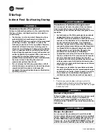
NOTICE
Meter Damage!
Measuring voltage with meter connect to a circuit
could result in meter damage. Do NOT measure voltage
with meter connected to a circuit.
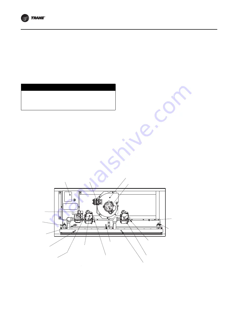
Figure 42.
Indirect fired gas furnace components
INDUCER MOTOR
IGNITION
CONTROLLERS
ON/OFF GAS VALVE
ON/OFF GAS VALVE
MANIFOLD GAS
PRESSURE TAP
AIR-PROVING
SWITCH
MINIMUM/MAXIMUM INLET PRESSURE =
7 IN. WC/14 IN. WC (1.7 KPA/3.5 KPA)
FOR NATURAL GAS AND 10 IN. WC/14 IN. WC
(2.5 KPA/3.5 KPA) FOR PROPANE
MANIFOLD GAS
PRESSURE TAP 3.5 in. wc
ROLLOUT SWITCH
MINIMUM/MAXIMUM INLET PRESSURE =
7 IN. WC/14 IN. WC (1.7 KPA/3.5 KPA)
FOR NATURAL GAS AND 10 IN. WC/14 IN. WC
(2.5 KPA/3.5 KPA) FOR PROPANE
CONDENSATE DRAIN
(TYP. 2)
INDUCER BLOWER
MODULATING VALVE
INLET PRESSURE TAP
5 in. wc
FLAME
SENSOR
HIGH LIMIT
SWITCH
ROLLOUT
SWITCH
MODULATING
GAS VALVE

