


Installation: Mechanical
Chiller Isolation
To minimize sound and vibration transmission through the building structure, and to
assure proper weight distribution over the mounting surface, install isolation pads or
spring isolators under the chiller feet.
Note: Isolation pads are provided with each chiller unless spring isolators are specified
on the sales order.
Specific isolator loading data is provided in the until submittal package. Also refer to
Table 10. If necessary, contact your local Trane sales office for further information.
Isolation Pads
When the unit is ready for final placement, position isolation pads end-to-end under
the full length of the chiller leg. The pads measure 6" x 18" (152 x 457mm). See Figure
15. No gaps should be present between pads.
Remember that the chiller must be level within 1/4" (6 mm) over its length and width
after it is lowered onto the isolation pads. In addition, all piping connected to the
chiller must be properly isolated and supported so that it does not place any stress on
the unit.
Figure 15. Isolation pad
5/16-3/8
"
(8-10 mm)
Spring Isolators
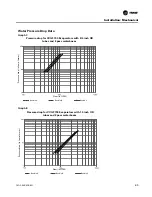
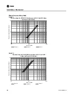
Spring isolators should be considered whenever chiller installation is planned for an
upper-story location. Spring isolator selection and placement information is presented
in Figure 16 and Figure 17.
Note: Three types of spring isolators, shown in Tables 11-13 are used. Each type has its
own maximum loading characteristics.
Spring isolators are typically shipped assembled and ready for installation. To install
and adjust the isolators properly, follow the instructions given.
Note: Do not adjust the isolators until the chiller is piped and charged with refrigerant
and water.
1. Position the spring isolators under the chiller as shown in Figure 16 and Figure 18.
Make sure that each isolator is centered in relation to the tube sheet.
2. Set isolators on the sub-base; shim or grout them as necessary to provide a flat,
level surface as the same elevation for all mountings. Be sure to support the full un-
derside of the isolator base plate; no not straddle gaps or small shims.
3. If required, bolt the isolators to the floor through the slots provided, or cement the
pads.
Note:
fastening the isolators to the floor is not necessary unless specified.
4. If the chiller must be fastened to the isolators, insert cap screws through the chiller
base and into the holes tapped in the upper housing of each isolator. Do not allow
the screws to protrude below the underside of the isolator upper housing. An al-
ternative method of fastening the chiller to the isolators is to cement the neoprene
pads.
5. Set the chiller on the isolators; refer to the "Rigging" section for lifting instructions.
CVGF-SVX03B-EN
51
Содержание CVGF1000
Страница 6: ...TRMM Tracer Communications UCP Unit Control Panel CVGF SVX03B EN 6 General Information...
Страница 125: ......
Страница 126: ......
Страница 127: ......


