User's Manual l MBa8MPxL UM 0100 l © 2022, TQ-Systems GmbH
Page 16
3.3.5
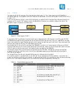
PCIe M.2
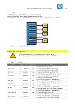
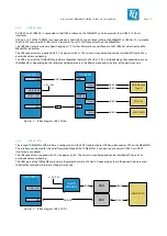
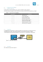
The processor i.MX 8M Plus provides a PCIe Gen3 interface with one lane (x1). This is fully provided by the TQMa8MPxL in
standard multiplexing. It is compatible with the PCI Express Base Specification, revision 3.0 and supports transfer rates of 2.5 GT/s
as well as 5 GT/s.
For PCIe, the connection of a plug-in card in the M.2 form factor is provided. The M.2 standard defines different codings for the
connector, an M.2 slot with "A+E" coding is used on the MBa8MPxL. M.2 modules are available in different form factors. The
MBa8MPxL supports the common 2230 form factor.
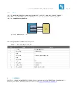
TQMa8MPxL
PCIe
I2C1
M.2
slot
USB hub
TUSB8041
LED
SIM card
Clock
generator
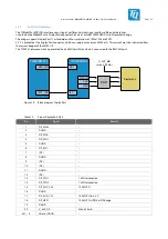
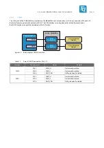
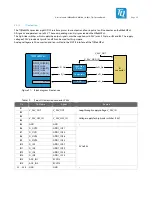
Figure 13: Block diagram PCIe M.2
As required by the M.2 specification, the motherboard's power budget provides 2 A for the plug-in card.
The signals PERST0#
and PEWAKE0# required for power mode control are connected to GPIOs of the CPU with 0 Ω resistors. CLKREQ0# on the other
hand is connected to the input of the clock generator, which controls the clock channel of the M.2 card. The second input of the
clock generator for the clock to the CPU is controlled by another GPIO.
Connected to the M.2 slot are the PCIe interface of the TQMa8MPxL, as well as a 3.3 V power supply. Furthermore, a USB host
(from the USB hub) and an I2C interface are connected next to the PCIe lane. When using the I2C functionality, check in advance
if the I2C address used by the plug-in card is not already used by a peripheral on the MBa8MPxL.
The reference clock for PCIe is provided by the external clock generator 9FGV0241. The clock generator can optionally be
connected to the I2C bus with 0 Ω resistors. Via the I2C bus, individual outputs can be switched off and the slew rate and
amplitude can be changed.
Any standard PCIe card can be used, provided that the necessary software drivers are available.
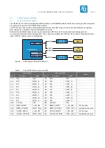
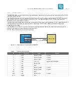
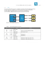
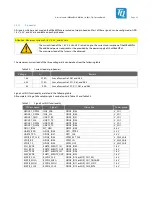
A micro SIM card holder is provided for the use of a GSM card. Since a combination of A-E-Key and B-Key is required for the
proper use of a SIM card according to the standard, an unpopulated pin header is also provided. All signals required for the B-Key
(pins 30, 32, 34, 36 and 66) are available on this, so customers can connect an adapter cable to a B-Key to it.
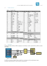
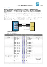
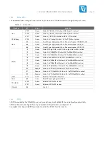
Table 10:
Pinout SIM card connector, X46
Pin
Signal
Not
C1 V_UIM_PWR
Connected to pin 68 (UIM_POWER_SNK) of the M.2 slot
C2 UIM_RST
Connected to pin 1 of header X557
C3 UIM_CLK
Connected to pin 2 of header X557
C4 (NC)
–
C5 GND
–
C6 UIM_SWP
Connected to pin 66 (UIM_SWP) of the M.2 slot
C7 UIM_DATA
Connected to pin 3 of header X557
C8 (NC)
–
DC SIM_DETECT
Connected to pin 5 of header X557
DS GND
–


