


User's Manual l MBa8MPxL UM 0100 l © 2022, TQ-Systems GmbH
Page 13
3.3
Communication interfaces
3.3.1
Ethernet 1000 Base-T (RGMII)
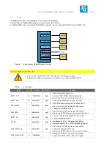
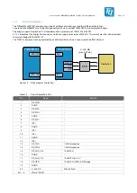
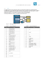
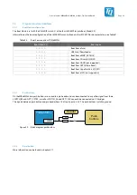
The i.MX 8M Plus CPU has two independent RGMII interfaces. On the MBa8MPxL both interfaces are used to provide two Gigabit
Ethernet ports by means of two DP83867 Ethernet PHYs.
The PHY has boot straps to start with adjustable default values. Some boot straps can be customized with placement options.
More information is available in the latest MBa8MPxL schematic.
Both interfaces additionally provide event signals according to IEEE 1588, which can be used to realize high precision
synchronizations between Ethernet components. These signals are available from ENET0 at X63 by default. If required, the event
signals of ENET1 can be used via assembly option.
TQMa8MPxL
RJ45
ENET_TSN
RGMII0
ENET_QOS
RGMII1
PHY #1
DP83867
PHY #2
DP83867
RJ45
EVENT1
EVENT2
SAI2
Pin
header
Figure 9:
Block diagram Ethernet 1000 Base-T
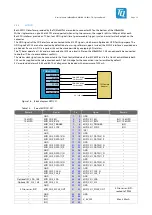
Table 8:
Pinout RJ45 Ethernet connector, X66
X66, left RJ45
X66, right RJ45
Remark
Pin
Pin name
Signal
Pin
Pin name
Signal
1A
GND
GND
1B
GND
GND
–
2A
TD0+
2B
TD0+
–
3A
TD0–
ENET0_A–
3B
TD0–
ENET1_A–
–
6A
TD1+
6B
TD1+
–
4A
TD1–
ENET0_B–
4B
TD1–
ENET1_B–
–
5A
TD2+
5B
TD2+
–
7A
TD2–
ENET0_C–
7B
TD2–
ENET1_C–
–
8A
TD3+
8B
TD3+
–
9A
TD4–
ENET0_D–
9B
TD4–
ENET1_D–
–
10A
CHS.GND
GND
10B
CHS.GND
GND
–
11A
GREEN_ANODE
V_3V3_MB
11B
GREEN_ANODE
V_3V3_MB
120 Ω in series
12A
GREEN_CATHODE
ENET0_LED_0
12B
GREEN_CATHODE
ENET1_LED_0
Switched by transistor
13A
YELLOW_ANODE
V_3V3_MB
13B
YELLOW_ANODE
V_3V3_MB
120 Ω in series
14A
YELLOW_CATHODE
ENET0_LED_2
14B
YELLOW_CATHODE
ENET1_LED_2
Switched by transistor