


User's Manual l MBa8MPxL UM 0100 l © 2022, TQ-Systems GmbH
Page 9
3.1.3
I
2
C devices, address mapping
The TQMa8MPxL provides four I
2
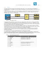
C buses. Of these, only I2C6 is provided on a pin header. All other buses are used by different
components on the module or the mainboard. All I2C buses provided by the TQMa8MPxL have a 3.3 V level. In order to be able
to connect 1.8 V components as well, two level converters are used on the MBa8MPxL. One is permanently connected to I2C4,
the second can be varied in its connection, but uses I2C2 by default.
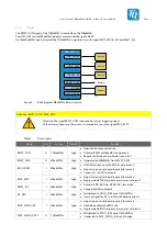
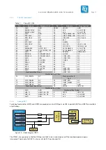
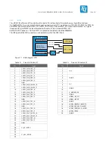
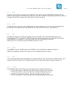
The following block diagram shows the I
2
C bus structure.
Video
Connectors
TQMa8MPxL
SE97BTP
Header
24LC64T
PCF85063
I2C1
I2C2
I2C6
Temperature
PCIe (M.2)
Level
shifter
PCIe Clock
MIPI_CSI[1..0]_I2C
I2C6
HDMI_I2C
3V3
1V8
HDMI_DDC
AudioCodec
PCA9450
DP Bridge
USB Hub
I2C4
Level
shifter
3V3
3V3
HDMI signal
conditioning chip
1V8
NP
N
P
NP
Figure 5:
Block diagram I
2
C bus
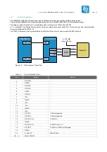
The following table shows the addresses used on the TQMa8MPxL and the MBa8MPxL.
Table 4:
I
2
C devices, address mapping on TQMa8MPxL and MBa8MPxL
Location
Device
Function
7-bit address
Remark
TQMa8MPxL
PCA9450
System Controller
0x25 / 010 0101b
Should not be altered
PCF85063
RTC
0x51 / 101 0001b
Optional
24LC64T
EEPROM
0x57 / 101 0111b
Optional
SE97BTP
Temperature sensor
0x1B / 001 1011b
–
EEPROM
0x33 / 011 0011b
R/W access in Protected Mode
0x53 / 101 0011b
R/W access in Normal Mode
SE050
Trust Secure Element
0x48 / 100 1000b
Optional
MBa8MPxL
TLV320AIC3204
Audio Codec
0x18 / 001 1000b
N7
SE97B
Temperature sensor
0x1C / 001 1100b
D1
EEPROM
0x34 / 011 0100b
D1, R/W access in Protected Mode
0x54 / 101 0100b
D1, R/W access in Normal Mode
TUSB8041
USB 3.0 Hub
0x44 / 100 0100b
D39, optional
9FGV0441A
Clock Generator
0x6A / 110 1010b
D47
TC9595XBG
MIPI DSI to DP
0x0F / 000 1111b
D43
Socket
PCIe M.2
(Device dependent)
X48