


User's Manual l MBa8MPxL UM 0100 l © 2022, TQ-Systems GmbH
Page 12
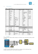
3.2
Power supply
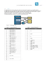
At X13, the MBa8MPxL has to be supplied with 24 V +10 % / –33 % (16 V to 26.4 V). All other voltages required on the MBa8MPxL
are derived from the supply voltage. 5 V (2.2 A), 3.3 V (1.75 A) and 1.8 V (0.75 A) are available at pin headers X61 and X63. It must
be ensured that the permissible limit values of the input circuitry are not exceeded.
The MBa8MPxL has a theoretical maximum power consumption of approx. 158.4 W at its 24 V supply connection. This
corresponds to a maximum typical current of 6.6 A at 24 V. The power supply unit used must be selected accordingly. In most
applications, however, the power consumption will be significantly lower and the MBa8MPxL including TQMa8MPxL consumes
approx. 5 W to 6 W when the i.MX 8M Plus operates at 100 % load. Most of the theoretically possible power consumption results
from the standard-compliant supply of the USB, PCIe (M.2) and LVDS interfaces, as well as from the power available at the pin
headers.
V_24V
(max. 6.6 A)
V_5V_MOD
(max. 10 A)
LM25119
V_3V3_MB
(max. 7 A)
V_1V2_DP
AP7173
AP7361C
TPS54335
V_1V8
V_2V5_ETH
Buck
Key:
LDO/Switch
V_12V
(max. 1.3 A)
TQMa8MPxL
(PCA9450)
V_5V_SW
Power Rail
Optional usage
on MBa8MPxL
V_1V8_MOD
(max. 0.5 A)
PFET
V_3V3_MOD
(max. 0.5 A)
AP7361C
V_1V1_USB
AP7361C
V_1V0_ETH
V_3V3_SD
(max. 0.4 A)
Optional usage
on MBa8MPxL
Supply for SD card
on MBa8MPxL
AP7361C
V_24V_OUT
V_24V_HSS_IN
Component
High side
switch
Optional bridge
at X555
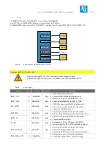
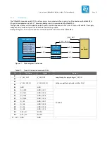
Figure 7:
Block diagram power supply MBa8MPxL
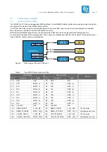
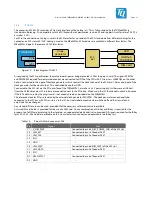
3.2.1
Protective circuitry
The protective circuit (see Figure 8) features the following characteristics:
•
Overcurrent protection by fuse 7 A, Slow Blow
•
Overvoltage protection
•
PI filter
•
Reverse polarity protection
•
Capacitors for voltage smoothing
V_24V
(max. 6.6 A)
7 A fuse,
Slow Blow
Filter
Reverse
Polarity
Protection
TVS Diode
Figure 8:
MBa8MPxL protective circuit