


FI-66
EFI SYSTEM — Air Induction System
3.
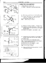
INSPECT THROTTLE POSITION SENSOR
(See step 2 on page FI-64)
4.
IF NECESSARY, ADJUST THROTTLE POSITION
SENSOR
(a) Loosen the two set screws of the sensor.
(b)
Insert a 0.93 mm (0.0366 in.) thickness gauge, be-
t ween the throttle stop screw and stop lever.
(c)
Connect the test probe of an ohmmeter to the termi-
nals IDL and E2 of the sensor.
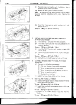
(d)
Gradually turn the sensor clockwise until the ohm-
meter deflects, and secure it with the two screws.
(e)
Recheck the continuity between terminals IDL and
E2.
Clearance between
lever and stop screw
Conitinuity (IDL— E2)
0.77 mm (0.0303 in.)
Continuity
1.09 mm (0.0429 in.)
No continuity
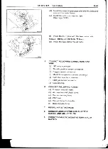
I NSTALLATION OF THROTTLE BODY
1.
INSTALL THROTTLE BODY
Install a new gasket and the throttle body with the three
bolts and nut.
Torque: 120 kg-cm (9 ft-lb, 12 N•m)
2.
CONNECT WATER HOSES
3.
CONNECT VACUUM HOSES
4.
CONNECT THROTTLE POSITION SENSOR
CONNECTOR
5.
CONNECT AIR CLEANER HOSE
6.
CONNECT ACCELERATOR AND THROTTLE
CABLES, AND ADJUST THEM
7.
FILL WITH ENGINE COOLANT


