


FI2502
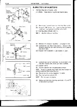
Throttle Lever
U
C^
No Clearance 0
Throttle Stop
Screw
F12355
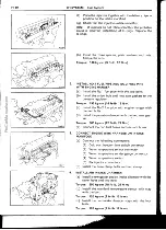
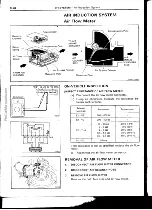
EFI SYSTEM — Air Induction System
FI-65
VC
1ti
VTA
IIJ
^^
^j_l—EDL
^
\
E2
IDL
VIA
VC
F10507
Clearance between
lever and stop screw
Between terminals
Resistance
0mm(0in.)
VTA—E2
0.3-6.3kQ
0.77 mm (0.0303 in.)
I DL — E2
Less than 2.3 kQ
1.09 mm (0.0429 in.)
IDL— E2
Infinity
Throttle valve fully
ope
opened position
VTA—E2
3.5-10.3kQ
VC — E2
4.25 — 8.25 kQ
(d) Reconnect the sensor connector.
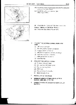
REMOVAL OF THROTTLE BODY
1.
DRAIN ENGINE COOLANT
2.
DISCONNECT ACCELERATOR AND THROTTLE
CABLES
3.
DISCONNECT AIR CLEANER HOSE
4.
DISCONNECT THROTTLE POSITION SENSOR
CONNECTOR
5.
DISCONNECT WATER HOSES
6.
DISCONNECT VACUUM HOSES
7.
REMOVE THROTTLE BODY
Remove the three bolts, nut, throttle body and gasket
I NSPECTION OF THROTTLE BODY
1. CLEAN THROTTLE BODY
(a)
Using a soft brush and carburetor cleaner, clean the
cast parts.
(b)
Using compressed air, clean all the passages and
apertures.
NOTICE: To prevent deterioration, do not clean the
throttle position sensor.
2. INSPECT THROTTLE VALVE
Check that there is no clearance between the throttle
stop screw and throttle lever when the throttle valve is
fully closed.