FU-24 FUEL SYSTEM - Injection Nozzles (1 HD-T)
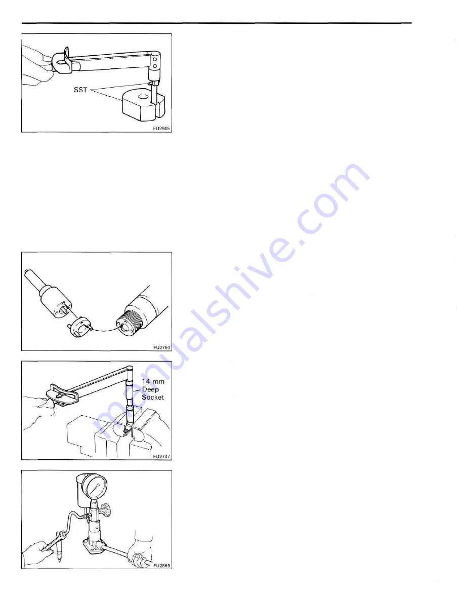
(i) After checking the No.2 opening pressure, remove the
capsule sub-assembly and tighten the plug screw with
SST.
SST 09268-17010
Torque: 25 kg-cm (21 in.-lb, 2.5 N-m)
3. ADJUST NO.1 OPENING PRESSURE
(a) Assemble the nozzle holder body, adjusting shim
selected in step 1, the capsule sub- assembly, adjust-
ing shim for adjustment of No.1 opening pressure,
No.1 pressure spring, No.1 pressure pin, distance
piece, straight pins and the nozzle sub-assembly, and
finger tighten the retaining nut.
HINT:
• Align the holes of the nozzle body, distance piece and
nozzle holder body.
• When the thickness of the originally used adjusting shim
is not known, use a shim 1.5 mm (0.59 in.) thick instead.
(b) Using a 14 mm deep socket wrench, torque the
retaining nut.
Torque: 350 kg-cm (25 ft-lb, 34 N-m)
NOTICE: Over torquing could cause nozzle deforma-
tion and needle adhesion or other defects.
(c) Install the injection nozzle to the injection nozzle hand
tester and bleed air from the union nut.
CAUTION: Do not place your finger over the nozzle
injection hole.
Содержание 1HD-T
Страница 1: ......
Страница 53: ...EM 42 ENGINE MECHANICAL Timing Gears TIMING GEARS COMPONENTS ...
Страница 65: ...EM 54 ENGINE MECHANICAL Cylinder Head CYLINDER HEAD COMPONENTS ...
Страница 95: ...EM 84 ENGINE MECHANICAL Cylinder Block CYLINDER BLOCK COMPONENTS ...
Страница 133: ...TURBOCHARGER SYSTEM Turbocharger TC 9 COMPONENTS ...
Страница 145: ...FU 6 FUEL SYSTEM Fuel Heater System FUEL HEATER SYSTEM SYSTEM CIRCUIT ...
Страница 166: ...FUEL SYSTEM Injection Pump FU 27 INJECTION PUMP REMOVAL OF INJECTION PUMP ...
Страница 169: ...FU 30 FUEL SYSTEM Injection Pump COMPONENTS ...
Страница 170: ...FUEL SYSTEM Injection Pump FU 31 COMPONENTS Cont d ...
Страница 171: ...FU 32 FUEL SYSTEM Injection Pump COMPONENTS Cont d ...
Страница 251: ...LU 4 LUBRICATION SYSTEM Troubleshooting TROUBLESHOOTING ...
Страница 255: ...LU 8 LUBRICATION SYSTEM Oil Pump OIL PUMP COMPONENT ...
Страница 262: ...LUBRICATION SYSTEM Oil Cooler Relief Valve and Check Valve LU 15 OIL COOLER RELIEF VALVE AND CHECK VALVE COMPONENTS ...
Страница 272: ...ST 4 STARTING SYSTEM Pre Heating System Super Glow Type TIMER CHARACTERISTIC DIAGRAM Cont d ...
Страница 281: ...STARTING SYSTEM Troubleshooting Starting System Circuit ST 13 TROUBLESHOOTING STARTING SYSTEM CIRCUIT ...
Страница 282: ...ST 14 STARTING SYSTEM Starting System Circuit STARTING SYSTEM CIRCUIT Cont d ...
Страница 340: ...B 1 STANDARD BOLT TORQUE SPECIFICATIONS Page STANDARD BOLT TORQUE SPECIFICATIONS B 2 ...
Страница 343: ...C 1 SSTAND SSM Page SST SPECIAL SERVICE TOOLS C 2 SSM SPECIAL SERVICE MATERIALS C 6 ...


