EM-65
ENGINE MECHANICAL - Cylinder Head
(b) Using a micrometer, measure the diameter of the valve
stem.
Valve stem diameter:
Intake 7.975-7.990 mm
(0.3140-0.3146 in.)
Exhaust 7.960-7.975 mm
(0.3134-0.3140 in.)
(c) Subtract the valve stem diameter measurement from
the guide bushing inside diameter measurement.
Standard oil clearance:
Intake 0.020-0.055 mm
(0.0008-0.0022 in.)
Exhaust 0.035-0.070 mm
(0.0014-0.0028 in.)
Maximum oil clearance:
Intake 0.08 mm (0.0031 in.)
Exhaust 0.10 mm (0.0039 in.)
If the clearance is greater than maximum, replace the valve
and guide bushing.
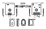
10. IF NECESSARY, REPLACE VALVE GUIDE BUSHINGS
(a) Using SST and a hammer, tap out the guide bushing.
SST 09201-60011
(b) Using a caliper gauge, measure the bushing bore
diameter of the cylinder head.
(c) Select a new guide bushing (STD size or 0/S 0.05).
If the bushing bore diameter of the cylinder head is greater
than 13.025 mm (0.5128 in.), machine the bushing bore to
the following dimension:
Rebored cylinder head bushing bore dimension:
13.054-13.075 mm (0.5139-0.5148 in.)
If the bushing bore diameter of the cylinder head is greater
than 13.075 mm (0.5148 in.), replace the cylinder head.
Содержание 1HD-T
Страница 1: ......
Страница 53: ...EM 42 ENGINE MECHANICAL Timing Gears TIMING GEARS COMPONENTS ...
Страница 65: ...EM 54 ENGINE MECHANICAL Cylinder Head CYLINDER HEAD COMPONENTS ...
Страница 95: ...EM 84 ENGINE MECHANICAL Cylinder Block CYLINDER BLOCK COMPONENTS ...
Страница 133: ...TURBOCHARGER SYSTEM Turbocharger TC 9 COMPONENTS ...
Страница 145: ...FU 6 FUEL SYSTEM Fuel Heater System FUEL HEATER SYSTEM SYSTEM CIRCUIT ...
Страница 166: ...FUEL SYSTEM Injection Pump FU 27 INJECTION PUMP REMOVAL OF INJECTION PUMP ...
Страница 169: ...FU 30 FUEL SYSTEM Injection Pump COMPONENTS ...
Страница 170: ...FUEL SYSTEM Injection Pump FU 31 COMPONENTS Cont d ...
Страница 171: ...FU 32 FUEL SYSTEM Injection Pump COMPONENTS Cont d ...
Страница 251: ...LU 4 LUBRICATION SYSTEM Troubleshooting TROUBLESHOOTING ...
Страница 255: ...LU 8 LUBRICATION SYSTEM Oil Pump OIL PUMP COMPONENT ...
Страница 262: ...LUBRICATION SYSTEM Oil Cooler Relief Valve and Check Valve LU 15 OIL COOLER RELIEF VALVE AND CHECK VALVE COMPONENTS ...
Страница 272: ...ST 4 STARTING SYSTEM Pre Heating System Super Glow Type TIMER CHARACTERISTIC DIAGRAM Cont d ...
Страница 281: ...STARTING SYSTEM Troubleshooting Starting System Circuit ST 13 TROUBLESHOOTING STARTING SYSTEM CIRCUIT ...
Страница 282: ...ST 14 STARTING SYSTEM Starting System Circuit STARTING SYSTEM CIRCUIT Cont d ...
Страница 340: ...B 1 STANDARD BOLT TORQUE SPECIFICATIONS Page STANDARD BOLT TORQUE SPECIFICATIONS B 2 ...
Страница 343: ...C 1 SSTAND SSM Page SST SPECIAL SERVICE TOOLS C 2 SSM SPECIAL SERVICE MATERIALS C 6 ...