EM-66
ENGINE MECHANICAL - Cylinder Head
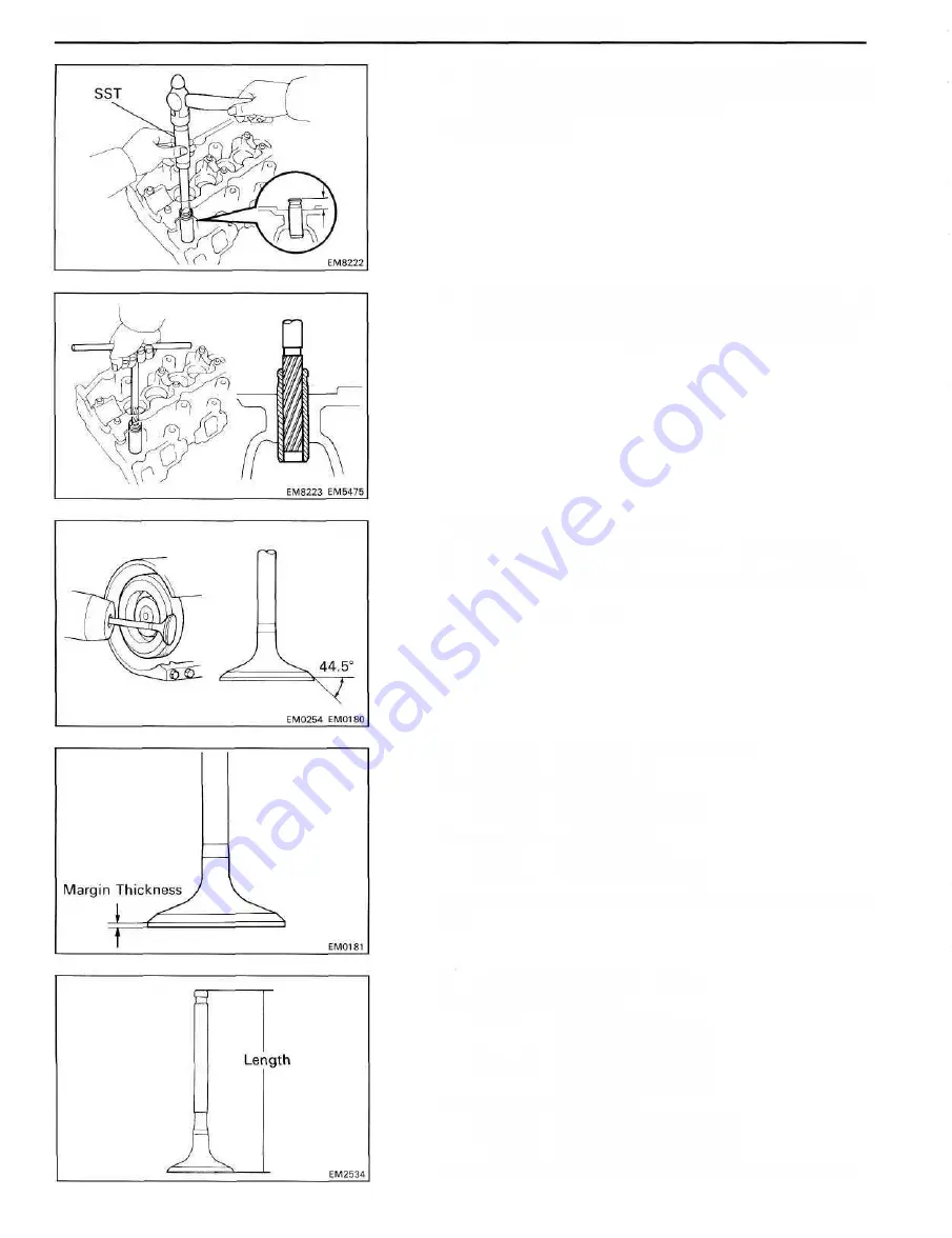
(d) Using SST and a hammer, tap in a new guide bushing
to where there is 11.8 - 12.2 mm (0.465 - 0.480 in.)
protruding from the cylinder head.
SST 09201-60011
(e) Using a sharp 8 mm reamer, ream the guide bushing to
obtain the standard specified clearance (See page
EM-65) between the guide bushing and valve stem.
11. INSPECT AND GRIND VALVES
(a) Grind the valve enough to remove pits and carbon.
(b) Check that the valve is ground to the correct valve face
angle.
Valve face angle: 44.5°
(c) Check the valve head margin thickness.
Standard margin thickness:
Intake 1.6 mm (0.063 in.)
Exhaust 1.7 mm (0.067 in.)
Minimum margin thickness:
Intake 1.1 mm (0.043 in.)
Exhaust 1.2 mm (0.047 in.)
If the margin thickness is less than minimum, replace the
valve.
(d) Check the valve overall length.
Standard overall length:
Intake 103.29-103.69 mm
(4.0665-4.0823 in.)
Exhaust 103.14-103.54 mm
( 4 . 0 6 0 6 - 4 . 0 7 6 4 in.)
Minimum overall length:
Intake 102.79 mm (4.0468 in.)
Exhaust 102.64 mm (4.0409 in.)
If the overall length is less than minimum, replace the valve.
Содержание 1HD-T
Страница 1: ......
Страница 53: ...EM 42 ENGINE MECHANICAL Timing Gears TIMING GEARS COMPONENTS ...
Страница 65: ...EM 54 ENGINE MECHANICAL Cylinder Head CYLINDER HEAD COMPONENTS ...
Страница 95: ...EM 84 ENGINE MECHANICAL Cylinder Block CYLINDER BLOCK COMPONENTS ...
Страница 133: ...TURBOCHARGER SYSTEM Turbocharger TC 9 COMPONENTS ...
Страница 145: ...FU 6 FUEL SYSTEM Fuel Heater System FUEL HEATER SYSTEM SYSTEM CIRCUIT ...
Страница 166: ...FUEL SYSTEM Injection Pump FU 27 INJECTION PUMP REMOVAL OF INJECTION PUMP ...
Страница 169: ...FU 30 FUEL SYSTEM Injection Pump COMPONENTS ...
Страница 170: ...FUEL SYSTEM Injection Pump FU 31 COMPONENTS Cont d ...
Страница 171: ...FU 32 FUEL SYSTEM Injection Pump COMPONENTS Cont d ...
Страница 251: ...LU 4 LUBRICATION SYSTEM Troubleshooting TROUBLESHOOTING ...
Страница 255: ...LU 8 LUBRICATION SYSTEM Oil Pump OIL PUMP COMPONENT ...
Страница 262: ...LUBRICATION SYSTEM Oil Cooler Relief Valve and Check Valve LU 15 OIL COOLER RELIEF VALVE AND CHECK VALVE COMPONENTS ...
Страница 272: ...ST 4 STARTING SYSTEM Pre Heating System Super Glow Type TIMER CHARACTERISTIC DIAGRAM Cont d ...
Страница 281: ...STARTING SYSTEM Troubleshooting Starting System Circuit ST 13 TROUBLESHOOTING STARTING SYSTEM CIRCUIT ...
Страница 282: ...ST 14 STARTING SYSTEM Starting System Circuit STARTING SYSTEM CIRCUIT Cont d ...
Страница 340: ...B 1 STANDARD BOLT TORQUE SPECIFICATIONS Page STANDARD BOLT TORQUE SPECIFICATIONS B 2 ...
Страница 343: ...C 1 SSTAND SSM Page SST SPECIAL SERVICE TOOLS C 2 SSM SPECIAL SERVICE MATERIALS C 6 ...


