EM-20
ENGINE MECHANICAL - Engine Tune-Up
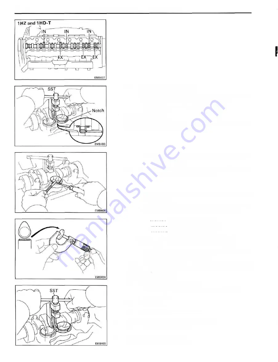
(d) Remove the adjusting shim.
• Turn the crankshaft to position the cam lobe of the
camshaft on the adjusting valve upward.
• Using SST, press down the valve lifter.
SST 09248-64011
HINT: Before pressing down the valve lifter, position the
notch on the exhaust manifold side.
• Remove the adjusting shim with a small screwdriver
and magnetic finger.
(e) Determine the replacement adjusting shim size by
using following (Formula or Charts):
• Using a micrometer, measure the thickness of the
removed shim.
• Calculate the thickness of the new shim so the
valve clearance comes within specified value.
T Thickness of used shim
A Measured valve clearance
N Thickness of new shim
Intake N = T + (A-0.20 mm (0.008 in.))
Exhaust N = T + (A-0.40 mm (0.016 in.))
• Select a new shim with a thickness as close as
possible to the calculated values.
HINT: Shims are available in twenty sizes in increments
of 0.05 mm (0.0020 in.), from 2.35 mm (0.0925 in.) to
3.30 mm (0.1299 in.)
(f) Install a new adjusting shim.
• Place a new adjusting shim on the valve lifter.
• Remove SST.
SST 09248-64011
(g) Recheck the valve clearance.
5. REINSTALL CYLINDER HEAD COVER
(See step 2 on page EM -38)
6. REINSTALL INTAKE PIPE
(See step 3 on page EM-38)
Содержание 1HD-T
Страница 1: ......
Страница 53: ...EM 42 ENGINE MECHANICAL Timing Gears TIMING GEARS COMPONENTS ...
Страница 65: ...EM 54 ENGINE MECHANICAL Cylinder Head CYLINDER HEAD COMPONENTS ...
Страница 95: ...EM 84 ENGINE MECHANICAL Cylinder Block CYLINDER BLOCK COMPONENTS ...
Страница 133: ...TURBOCHARGER SYSTEM Turbocharger TC 9 COMPONENTS ...
Страница 145: ...FU 6 FUEL SYSTEM Fuel Heater System FUEL HEATER SYSTEM SYSTEM CIRCUIT ...
Страница 166: ...FUEL SYSTEM Injection Pump FU 27 INJECTION PUMP REMOVAL OF INJECTION PUMP ...
Страница 169: ...FU 30 FUEL SYSTEM Injection Pump COMPONENTS ...
Страница 170: ...FUEL SYSTEM Injection Pump FU 31 COMPONENTS Cont d ...
Страница 171: ...FU 32 FUEL SYSTEM Injection Pump COMPONENTS Cont d ...
Страница 251: ...LU 4 LUBRICATION SYSTEM Troubleshooting TROUBLESHOOTING ...
Страница 255: ...LU 8 LUBRICATION SYSTEM Oil Pump OIL PUMP COMPONENT ...
Страница 262: ...LUBRICATION SYSTEM Oil Cooler Relief Valve and Check Valve LU 15 OIL COOLER RELIEF VALVE AND CHECK VALVE COMPONENTS ...
Страница 272: ...ST 4 STARTING SYSTEM Pre Heating System Super Glow Type TIMER CHARACTERISTIC DIAGRAM Cont d ...
Страница 281: ...STARTING SYSTEM Troubleshooting Starting System Circuit ST 13 TROUBLESHOOTING STARTING SYSTEM CIRCUIT ...
Страница 282: ...ST 14 STARTING SYSTEM Starting System Circuit STARTING SYSTEM CIRCUIT Cont d ...
Страница 340: ...B 1 STANDARD BOLT TORQUE SPECIFICATIONS Page STANDARD BOLT TORQUE SPECIFICATIONS B 2 ...
Страница 343: ...C 1 SSTAND SSM Page SST SPECIAL SERVICE TOOLS C 2 SSM SPECIAL SERVICE MATERIALS C 6 ...


