


- 18 -
tousek
/ EN_ST-12-5_05 / 25. 03. 2020
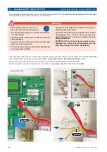
Important: Notes regarding
connection of a flashing light
•
Attention: Before carrying out
connection works, the power
supply of the facility has to be
turned off.
• A flashing light with 230V, max.
40W can be connected at the
terminals 10/11
11
10
2
1
0
The following two menu points can only be selected if the menu point additional menu is adjusted to „Courtyard-/Control
lamp“ (hence shown on display).
Courtyard lamp
(
Description add. modules page 19
)
Lights / Lamps
switched off
5–950 adjustable:
at the courtyard lamp output an external lamp can be connected (e.g. garden lamp), which can be
turned on for each opening command for the duration of adjusted time.
Control lamp
(
Description add. modules page 19)
Lights / Lamps
illuminates during open and close:
The pilot lamp output is activated during opening- and closing movement.
blinks slowly/illuminates/blinks:
The pilot lamp output is activated as follows: During opening the pilot lamp flashes
slowly. During pause time, in opened position or when the gate stops it is illuminated. During the closing movement
it flashes rapidly. If the gate is closed, the pilot lamp expires
illuminates in open position:
Pilot lamp is illuminated as soon as the gate has reached end position open.
•
Before taking off the housing cover the
main switch has to be turned off !
•
Follow safety instructions
(see page 8)
!
Warning
Prewarning OPEN
(terminals 10/11)
Lights / Lamps
switched off
1–30s adjustable:
before each opening movement the flashing light is activated for the adjusted time.
Prewarning CLOSE
(terminals 10/11)
Lights / Lamps
switched off
1–30s adjustable:
before each closing movement the flashing light is activated for the adjusted time.
Lights / Lamps
Connections and adjustments
•
Before taking off the housing cover the
main switch has to be turned off !
•
Follow safety instructions
(see page 8)
!
Warning
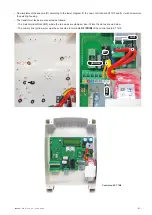
Peripherals
Connections and adjustments
Electric lock
• To terminals 72/73, an e-lock 12V
DC, max. 15W can be connected.
•
Only electric locks that are
designed for 12V DC, can be
connected.
12V DC, max. 15W
72 73
Electric lock
(terminals 72/73)
Peripherals
switched off
1–10s adjustable:
The electric lock is activated by
push button impulse or impulse from pedestrian button
for a period of time set here to ensure the release
depending on the gate situation
+ –


