FILE NO. SVM-13072
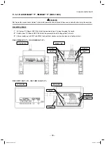
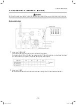
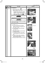
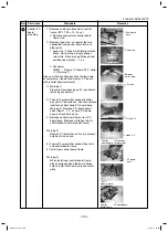
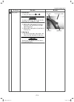
Remove the connectors
with locking function by
pushing the part indicated
by the arrow mark.
No.
3
Part name
Inverter
assembly
Procedure
Remarks
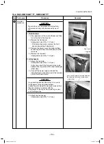
REQUIREMENT
As each connector has a lock mechanism,
avoid to remove the connector by holding the
lead wire, but by holding the connector.
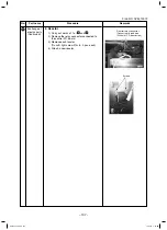
s#ONNECTOR
#ONNECTIONTOCOMPRESSOR
・・・
(3P
:
Relay
connector white
)
※
(
Warning 1)
Reactor
(
2P
:
Relay connector white)
#.
・・・
Outdoor fan
(
3P
:
white)
※
(
Warning 1)
#.
・・・
4 directional valve
(
3P
:
yellow)
※
(Warning 1)
#.
・・・
PMV coil
(
6P
:
white)
※
(Warning 1)
#.
・・・
TD sensor (3P
:
white)
#.
・・・
TS sensor (3P
:
white)
※
(
Warning 1)
#.
・・・
TE sensor (2P
:
white)
※
(
Warning 1)
#.
・・・
TL sensor (2P : white)
※
(
Warning 1)
#.
・・・
TO sensor (2P
:
white)
#.
・・・
#ASETHERMO0BLUE
)
※
(
Warning 1)
#.
・・・
High pressure switch (3P : green)
※
(
Warning 1)
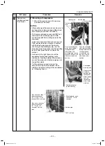
※
Warning 1)
Please remove housing part’s lock before
removing connectors.
Inverter
assembly
– 99 –
SVM-13072.indb 99
SVM-13072.indb 99
11/01/13 1:53 PM
11/01/13 1:53 PM
Содержание RAV-SM1104ATJP-E
Страница 116: ...FILE NO SVM 13072 Inverter assembly SM56 116 SVM 13072 indb 116 SVM 13072 indb 116 11 01 13 1 54 PM 11 01 13 1 54 PM ...
Страница 120: ...FILE NO SVM 13072 Inverter assembly SM80 120 SVM 13072 indb 120 SVM 13072 indb 120 11 01 13 1 54 PM 11 01 13 1 54 PM ...
Страница 127: ...FILE NO SVM 13072 127 SVM 13072 indb 127 SVM 13072 indb 127 11 01 13 1 54 PM 11 01 13 1 54 PM ...


