FILE NO. SVM-13072
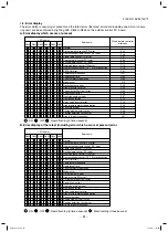
Various displays and various operations are enabled by push buttons (service) switches and LED on the
outdoor control P.C. board.
Service switch (SW01, SW02) operations
LED display
s
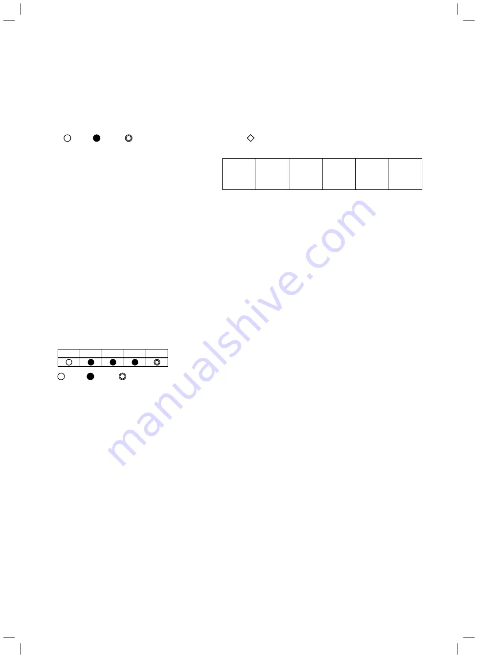
4 patterns are provided for LED display.
: ON,
: OFF,
: Rapid flashing (5 times/second),
: Slow flashing (Once/second)
D800 D801 D802 D803 D804
s
In the initial status of LED display, D805 is
ON as the right figure.
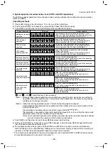
9-3-1. Refrigerant recovery control
HFC refrigerant is “Ozone layer destructive coefficient = 0”. However the discharge regulation is established for
HFC refrigerant as it is greenhouse gas.
For this Model, a switch is mounted for refrigerant recovery operation (pump down) by the outdoor unit so that
this Model can easily react to the environment when it will be reinstalled or scrapped.
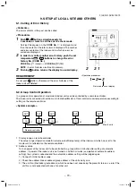
[Operating method]
1) Set fan operation to the indoor unit.
2) Check LED display is the initial status. If it is not so, set the initial status.
3) Push and hold SW01 for 5 seconds or more and then check D804 flashes slowly.
4) Push SW01 several times and then stop it at the point where LED display (D800 to D804) is indicated as
the following table.
: ON,
: OFF,
: Rapid flashing (5 times/second)
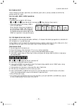
5) Push SW02 so that D805 flashes rapidly.
6) Push and hold SW02 for 5 seconds or more. The forced cooling operation star ts if D804 flashes slowly
and D805 is turned on. (Max. 10 minutes)
7) After operation for 3 minutes or more, close the valve at liquid side.
8) After recovery of refrigerant, close the valve at gas side.
9) Push and hold SW01 and SW02 for 5 seconds or more simultaneously. The LED returns to the initial
status, the cooling operation stops and the indoor fan operation stops.
10)Turn off the power supply.
* If an unknown point generated on the way of the operation, push and hold SW01 and SW02 for 5 seconds
or more simultaneously. You can return to the item 2).
When the initial status does not appear (in
case of flashing of D805), LED display can
be returned to the initial status by pushing
and holding the service switches SW01 and
SW02 for 5 seconds or more simultaneously.
9-3. Outdoor Unit
LED display : initial status
●
or
◎
●
or
◎
●
or
◎
●
or
◎
●
or
◎
○
D800
D801
D802
D803
D804
D805
(Yellow) (Yellow) (Yellow) (Yellow) (Yellow)
(Green)
– 75 –
SVM-13072.indb 75
SVM-13072.indb 75
11/01/13 1:53 PM
11/01/13 1:53 PM
Содержание RAV-SM1104ATJP-E
Страница 116: ...FILE NO SVM 13072 Inverter assembly SM56 116 SVM 13072 indb 116 SVM 13072 indb 116 11 01 13 1 54 PM 11 01 13 1 54 PM ...
Страница 120: ...FILE NO SVM 13072 Inverter assembly SM80 120 SVM 13072 indb 120 SVM 13072 indb 120 11 01 13 1 54 PM 11 01 13 1 54 PM ...
Страница 127: ...FILE NO SVM 13072 127 SVM 13072 indb 127 SVM 13072 indb 127 11 01 13 1 54 PM 11 01 13 1 54 PM ...

