


28-EN
27-EN
– 14 –
EN
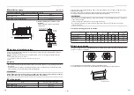
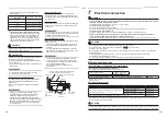
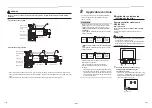
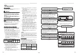
Wiring between indoor unit and outdoor unit
1. Figure below shows the wiring connections between the indoor and outdoor units and between the indoor units and
remote controller. The wires indicated by the broken lines or dot-and-dash lines are provided at the locally.
2. Refer to the both indoor and outdoor unit wiring diagrams.
3. The power of the indoor unit is supplied from the outdoor unit.
A B
1
1
2
2
3
3
A B
1
2
3
A B
1
1
2
2
3
3
Remote controller
Remote controller
Remote controller
inter-unit wiring
Indoor
side
Indoor power
inter-unit wiring
Remote controller wiring
Remote controller wiring
Indoor side
Indoor side
Indoor / Outdoor
connecting wires
Indoor / Outdoor
connecting wires
Outdoor side
Outdoor side
Power supply
Power supply
A B
1
2
3
A B
1
2
3
A B
1
2
3
A B
1
2
3
1
2
3
Remote controller
Remote controller
inter-unit wiring
Remote controller
inter-unit wiring
Remote controller
inter-unit wiring
Remote controller
wiring
Indoor side
Indoor side
Indoor side
Indoor side
Indoor power
inter-unit wiring
Triple
Double twin
Indoor power
inter-unit wiring
Indoor power
inter-unit wiring
Indoor / Outdoor
connecting wires
Outdoor side
Power supply
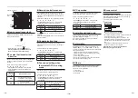
* Use 2-core shield wire (MVVS 0.5 to 2.0 mm
2
or more) for the remote controller wiring in the simultaneous twin,
simultaneous triple and simultaneous double twin systems to prevent noise problems. Connect both ends of the
shield wire to earth leads.
* Connect earth wires for each indoor unit in the simultaneous twin, simultaneous triple and simultaneous double
twin systems.
Wiring diagram
Single system
Simultaneous twin system
Simultaneous triple and double twin system
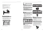
Communication type
TU2C-Link can be used with these models.
If the indoor unit and the connected remote controller / remote sensor are all TU2C-Link models, TU2C-Link
communication will be performed automatically.
(If the TCC-Link model is included, TCC-Link communication will be performed.)
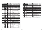
For details of communication type, refer to the following table.
Communication type and model names
Communication type
TU2C-Link
TCC-Link
Indoor unit
RAV-HM
½½½
series model
Other than RAV-HM
½½½
series
Wired remote
controller
RBC-A
½½
U
½½½
This letter indicates U series model.
Other than U series
Wireless remote
controller kit &
receiver unit
RBC-AXU
½½½
This letter indicates U series model.
Other than U series
Remote sensor
TCB-TC
½½
U
½½½
This letter indicates U series model.
Other than U series
CAUTION
When connecting to the central control device dedicated to TCC-Link, it is necessary to change to TCC-Link using a
wired remote controller. Set according to the Communication type procedure of “8 Applicable controls”.
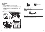
Indoor unit
Remote
controller
Indoor unit
Indoor unit
Indoor unit
Remote
controller
wiring
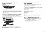
Remote controller inter-unit wiring
For number of max. connect-able units,
refer to the following table.
Ln
L2
L1
L
Max. number of connect-able indoor units, and communication type
Unit type
Indoor unit
RAV-HM
½½½
RAV-HM
½½½
*
*
Remote controller
Remote sensor
U series
*
U series
*
Communication type
TU2C-Link
TCC-Link
Max. number of connect-able units
16
8
*
: Other than RAV-HM
½½½
and U series


