


9
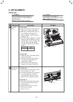
-2. Setup at Local Site / Others
Model name: TCB-PCNT30TLE2
9
-2-1. 1:1 Model Connection Interface (TCC-LINK adapter)
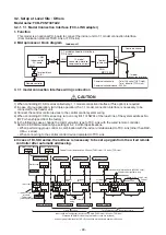
1. Function
This model is an optional P.C. board to connect the indoor unit to 1:1 model connection interface.
(Communication protocol:TU2C-Link or TCC-Link)
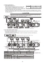
2. Microprocessor block diagram
CN51
CN40
SW01
Remote controller
Indoor control
P.C. board
1:1 model
connection interface
communication circuit
Terminal
resistance
1:1 model connection interface
P.C. board
MCC-1440
Indoor unit
1:1 model
connection interface
Communication units
: Total 128 units (TU2C-Link)
Total 64 units (TCC-Link)
Communication distance : 2000 m
CN50
CN41
Terminal block
(A, B)
Central controller
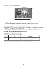
Indoor units in all refrigerant lines: Max. 128 units (TU2C-Link) / 64 units (TCC-Link)
[If mixed with SMMS (Link wiring), multi indoor units are included.]
*
However group follower units of SDI, DI series are not included in number of the units.
Central control device
Uh
U3 U4
Central control device
1 2 3
Central control devices: Max. 20 units (TU2C-Link) / 10 units (TCC-Link)
Refrigerant line 1
Outdoor unit
Indoor unit
1 2 3
Refrigerant line 2
1 2 3
Refrigerant line 3
1 2 3
Refrigerant line 4
1 2 3
A B
U3 U4
Uh
Uh
Uh
Caution 3
1 2 3
A B
U3 U4
1 2 3
A B
1 2 3
A B
1 2 3
A B
1 2 3
A B
U3 U4
1:1 model connection
interface
This product
sold separately
( )
Caution 1
Remote controller
Indoor/outdoor inter-unit wire (AC230V serial)
Central control system wiring
Header unit
Header
unit
Follower
unit
Follower
unit
Follower
unit
*
Wiring for No.1 and 2 only
Caution 2
Remote controller
Remote controller
Remote controller
Remote controller
wiring
)
e
l
p
i
r
t
f
o
e
l
p
m
a
x
E
(
n
o
i
t
a
r
e
p
o
e
l
p
i
r
T
/
n
i
w
T
Group operation
Uh
U3 U4
3. 1:1 model connection interface wiring connection
CAUTION
1) When controlling DI, SDI series collectively, 1:1 model connection interface (This option) is required.
2) In case of group operation, twin-triple operation, the 1:1 model connection interface is necessary to be
connected to the header unit.
3) Connect the central control devices to the central control system wiring.
4) When controlling DI, SDI series only, turn on only Bit 1 of SW01 of the least line of the system address No.
(OFF when shipped from the factory)
5) In the following cases, change the communication type to TCC-Link with the wired remote controller.
Refer to 28 Communication type setting of 5-2. Control Specifications.
• When performing group control in combination with the indoor unit dedicated to TCC-Link (other than RAV-
HM
∗∗∗
series).
• When connecting to the central control device dedicated to TCC-Link.
∗∗∗∗∗
In case of DI, SDI series, the address is necessary to be set up again from the wired remote
controller after automatic addressing.
- 90 -
Содержание RAV-HM1101CTP Series
Страница 18: ...2 CONSTRUCTION VIEWS EXTERNAL VIEWS Indoor Unit RAV HM401CTP RAV HM561CTP 18 ...
Страница 19: ...RAV HM801CTP 19 ...
Страница 20: ...RAV HM1101CTP RAV HM1101CTP RAV HM1401CTP RAV HM1601CTP 20 ...
Страница 24: ...4 WIRING DIAGRAM Indoor Unit 24 ...
Страница 118: ...144 9 MOO 5 BANGKADI INDUSTRIAL PARK TIVANON ROAD TAMBOL BANGKADI AMPHUR MUANG PATHUMTHANI 12000 THAILAND ...


