


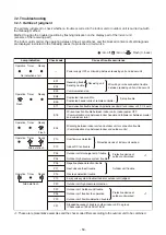


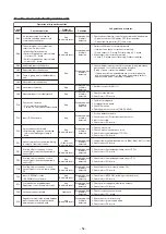


Trouble mode detected by indoor unit
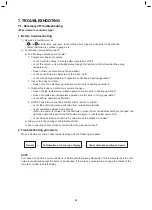
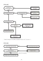
Operation of diagnostic function
Check
code
E03
E04
E08
L03
L07
L08
L09
L30
P10
P12
P19
P31
F01
F02
F10
F29
E11
E18
Cause of operation
No communication from remote
controller (including wireless) and
communication adapter
The serial signal is not output from
outdoor unit to indoor unit.
• Miswiring of inter-unit wire
• Serial communication circuit trouble
of outdoor P.C. board
• Serial communication circuit trouble
of indoor P.C. board
Duplicated indoor unit address
Duplicated indoor header unit
There is group wire in individual indoor
unit.
Unset indoor group address
Unset indoor capacity
Abnormal input of outside interlock
Float switch operation
• Float circuit, Disconnection,
Coming-off, Float switch contact trouble
Indoor DC fan trouble
4-way valve system trouble
• After heating operation has started,
indoor heat exchangers temp. is
down.
Unit automatically stops while warning
is output to other indoor units.
Coming-off, disconnection or short-
circuit of indoor heat exchanger temp.
sensor (TCJ)
Coming-off, disconnection or short-
circuit of indoor heat exchanger temp.
sensor (TC)
Coming-off, disconnection or short-
circuit of indoor room air temp. sensor
(TA)
Indoor EEPROM trouble
• EEPROM access trouble
Communication trouble between
Application control kit and indoor unit
Regular communication trouble between
indoor header and follower units and
between master and sub units
Status of
air conditioner
Stop
(Automatic reset)
Stop
(Automatic reset)
Stop
Stop
Stop
Stop
Stop
Stop
(Automatic reset)
Stop
(Follower unit)
(Automatic reset)
Stop
(Automatic reset)
Stop
(Automatic reset)
Stop
(Automatic reset)
Stop
(Automatic reset)
Stop
(Automatic reset)
Stop
(Automatic reset)
Condition
Displayed when
trouble is
detected
Displayed when
trouble is
detected
Displayed when
trouble is
detected
Displayed when
trouble is
detected
Displayed when
trouble is
detected
Displayed when
trouble is
detected
Displayed when
trouble is
detected
Displayed when
trouble is
detected
Displayed when
trouble is
detected
Displayed when
trouble is
detected
Displayed when
trouble is
detected
Displayed when
trouble is
detected
Displayed when
trouble is
detected
Displayed when
trouble is
detected
Displayed when
trouble is
detected
Judgment and measures
1. Check cables of remote controller and communication adapters.
• Remote controller LCD display OFF (Disconnection)
• C
• Check P.C. board (Indoor receiving / Outdoor sending).
entral remote controller [97] check code
1. Outdoor unit does not completely operate.
• Inter-unit wire check, correction of miswiring
• Check outdoor P.C. board. Correct wiring of P.C. board.
2. When outdoor unit normally operates
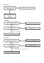
1. Check whether remote controller connection (Group/Individual)
was changed or not after power supply turned on
(Finish of group construction/Address check).
* If group construction and address are not normal when the
power has been turned on, the mode automatically shifts to
address setup mode. (Resetting of address)
1. Set indoor capacity (DN=11)
1. Check outside devices.
2. Check indoor P.C. board.
1. Trouble of drain pump
2. Clogging of drain pump
3. Check float switch.
4. Check Application control kit (TCB-PCUC2E)
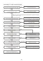
1. Position detection trouble
2. Check fan motor (Protective circuit operation).
3. Indoor fan locked.
4. Check indoor P.C. board.
1. Check 4-way valve.
2. Check 2-way valve and check valve.
3. Check indoor heat exchanger (TC/TCJ).
4. Check indoor P.C. board.
1. Judge follower unit while header unit is [E03], [L03], [L07] or [L08].
2. Check indoor P.C. board.
1. Check indoor heat exchanger temp. sensor (TCJ).
2. Check indoor P.C. board.
1. Check indoor heat exchanger temp. sensor (TC).
2. Check indoor P.C. board.
1. Check indoor room air temp. sensor (TA).
2. Check indoor P.C. board.
1. Check indoor EEPROM. (including socket insertion)
2. Check indoor P.C. board.
2. Check indoor P.C. board.
1. Check power supply/communication harness.
Occupancy sensor trouble
F30
Operation
Displayed when
trouble is
detected
2. Check indoor P.C. board.
1. Check occupancy sensor wiring.
1. Check remote controller wiring.
2. Check indoor power supply wiring.
3. Check indoor P.C. board.
- 54 -
Содержание RAV-HM1101CTP Series
Страница 18: ...2 CONSTRUCTION VIEWS EXTERNAL VIEWS Indoor Unit RAV HM401CTP RAV HM561CTP 18 ...
Страница 19: ...RAV HM801CTP 19 ...
Страница 20: ...RAV HM1101CTP RAV HM1101CTP RAV HM1401CTP RAV HM1601CTP 20 ...
Страница 24: ...4 WIRING DIAGRAM Indoor Unit 24 ...
Страница 118: ...144 9 MOO 5 BANGKADI INDUSTRIAL PARK TIVANON ROAD TAMBOL BANGKADI AMPHUR MUANG PATHUMTHANI 12000 THAILAND ...


