


– 99 –
Wrap the ferrite core with the compre
ss
or
lead wire for 1 time.
There
s
ho
u
ld
b
e no clearance
b
etween
s
o
u
nd-in
su
lation plate (
u
pper) and
s
o
u
nd-
in
su
lation plate (rolling o
u
t).
C
u
lt
u
ral rivet
C
u
lt
u
ral rivet
In
s
ert one
s
ide
In
s
ert one
s
ide
So
u
nd-in
su
lation plate
So
u
nd-in
su
lation plate
(rolling o
u
t)
(rolling o
u
t)
So
u
nd-in
su
lation plate
(
u
pper)
C
u
lt
u
ral rivet
In
s
ert one
s
ide
u
nder c
u
lt
u
ral rivet.
So
u
nd-in
su
lation plate
(rolling o
u
t)
Pa
ss
thro
u
gh
s
o
u
nd-
in
su
lation plate
(rolling o
u
t)
b
etween
su
ction pipe and
header pipe.
P
u
t the end of
s
o
u
nd-in
su
lation
plate (rolling o
u
t)
on the other end
at thi
s
po
s
ition.
Header pipe
Header pipe
S
u
ction pipe
S
u
ction pipe
Di
s
charge pipe
Di
s
charge pipe
Di
s
charge pipe
Pa
ss
thro
u
gh
s
o
u
nd-in
su
lation plate
(rolling in)
b
etween compre
ss
or and
di
s
charge pipe,
su
ction pipe and then p
u
t
the end of
s
o
u
nd-in
su
lation plate on the
other end at thi
s
po
s
ition.
Header pipe
S
u
ction pipe
Compre
ss
or lead
Compre
ss
or lead
Ferrite core
Ferrite core
Ferrite core
0 to 50
(Compre
ss
or lead po
s
itioning
s
tandard)
0 to 50
0
to
5
0
0 to 50
Compre
ss
or lead
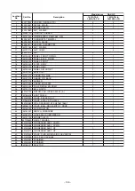
SW804
SW801
No.
10
Part name
Compre
ss
or
Compre
ss
or lead
(Contin
u
ed)
Procedure
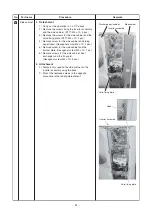
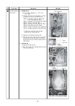
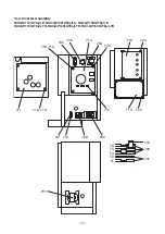
2. Mounting of compressor
1) Mo
u
nt the compre
ss
or in the rever
s
e
proced
u
re for removal.
NOTE
• After replacement of the compre
ss
or,
b
e
su
re
to replace the compre
ss
or lead. (Repair part
code of compre
ss
or lead: 43160612)
In thi
s
time, wrap the ferrite core with the
compre
ss
or lead wire
b
y 1 time.
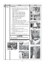
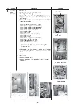
• A
s
s
hown in the right fig
u
re, mo
u
nt the
s
o
u
nd-in
su
lation plate (rolling in, rolling o
u
t)
b
y pa
ss
ing thro
u
gh it
b
etween the
compre
ss
or and the piping, and
b
etween the
piping and the partition
b
oard.
• Fix TD
s
en
s
or
b
y the
bu
ndling
b
and for heat-
proof on the market via the pipe cover
s
o that
TD
s
en
s
or doe
s
not directly come to contact
with the di
s
charge pipe.
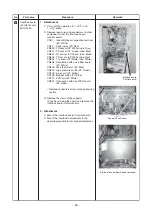
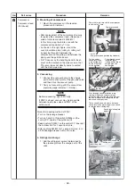
3
. Vacuuming
1) Connect the vac
uu
m p
u
mp to the charge
port and the check joint of the ga
s
pipe valve
and then drive the vac
uu
m p
u
mp.
2) Carry o
u
t vac
uu
ming
u
ntil the vac
uu
m low
pre
ssu
re ga
u
ge indicate
s
1 (mmHg).
NOTE
Before vac
uu
ming, open PMV f
u
lly.
If PMV i
s
clo
s
ed, vac
uu
m may
b
e impo
ss
i
b
le
b
etween li
qu
id pipe valve and PMV of the
o
u
tdoor
u
nit.
Forced f
u
ll-opening method of PMV
• T
u
rn on the leakage
b
reaker.
• T
u
rn on 1 and 3 of Dip
s
witch SW804 on the
control P.C.
b
oard of the o
u
tdoor
u
nit.
• Keep p
us
hing SW801 on the control P.C.
b
oard of
the o
u
tdoor
u
nit for 1
s
econd or more.
• After p
us
hing SW801 for 1
s
econd or more, t
u
rn
off the leakage
b
reaker within 2 min
u
te
s
.
4. Refrigerant charge
1) Add the refrigerant amo
u
nt determined
b
y
the pipe length from the charge port of the
valve.
Remarks
Содержание RAV-GP1101AT8-E
Страница 23: ... 23 4 WIRING DIAGRAM 4 1 Outdoor Unit RAV GP1101AT8 J E TR RAV GP1401AT8 J E TR RAV GP1601AT8 J E TR ...
Страница 103: ... 103 Outdoor Unit RAV GP1401AT8 E RAV GP1401AT8J E RAV GP1401AT8 TR RAV GP1401AT8J TR ...
Страница 105: ... 105 Outdoor Unit RAV GP1601AT8 E RAV GP1601AT8J E RAV GP1601AT8 TR RAV GP1601AT8J TR ...


