


– 85 –
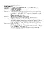
10-5. Confirmation of Indoor Unit No. Position
1. To know the indoor unit addresses though position of the indoor unit body is recognized
• In case of individual operation (Wired remote controller : indoor unit = 1 : 1)
(Follow to the procedure during operation)
1 2
END
Operation
<Operation procedure>
2
1
SET
TIME
TIMER SET
TEST
FILTER
LL
RESET
TEMP.
CL
FAN
SAVE
A
A
SWING/FIX
VENT
MODE
ON / OFF
UNIT LOUVER
T
1 2 3
END
<Operation procedure>
3
1
2
SET
TIME
TIMER SET
TEST
FILTER
LL
RESET
TEMP.
CL
FAN
SAVE
A
A
SWING/FIX
VENT
MODE
ON / OFF
UNIT LOUVER
T
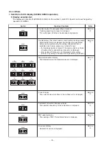
<Procedure>
1
Push
button if the unit stops.
2
Push
UNIT LOUVER
button (button of left side).
Unit No.
1-1
is displayed on LCD.
(It disappears after several seconds.)
The displayed unit No. indicate line address and indoor
unit address.
(When other indoor units are connected to the identical
remote controller (Group control unit), other unit
numbers are also displayed every pushing
UNIT LOUVER
button
(button of left side).
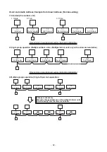
2. To know the position of indoor unit body by address
• To confirm the unit No. in the group control
(Follow to the procedure during operation) (in this procedure, the indoor units in group control stop.)
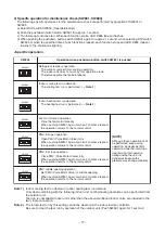
<Procedure>
The indoor unit numbers in the group control are
successively displayed, and fan, louver, and drain pump
of the corresponding indoor unit are turned on.
(Follow to the procedure during operation)
1
Push
and buttons simultaneously for
4 seconds or more.
• Unit No.
ALL
is displayed.
• Fans and louvers of all the indoor units in the
group control operate.
2
Every pushing
UNIT LOUVER
button (button of left
side), the unit numbers in the group control
are successively displayed.
• The unit No. displayed at the first time indicates the
master unit address.
• Fan and louver of the selected indoor unit only
operate.
3
Push button to finish the procedure.
All the indoor units in the group control
stop.
Содержание RAV-GP1101AT8-E
Страница 23: ... 23 4 WIRING DIAGRAM 4 1 Outdoor Unit RAV GP1101AT8 J E TR RAV GP1401AT8 J E TR RAV GP1601AT8 J E TR ...
Страница 103: ... 103 Outdoor Unit RAV GP1401AT8 E RAV GP1401AT8J E RAV GP1401AT8 TR RAV GP1401AT8J TR ...
Страница 105: ... 105 Outdoor Unit RAV GP1601AT8 E RAV GP1601AT8J E RAV GP1601AT8 TR RAV GP1601AT8J TR ...


