


– 92 –
So
u
nd-in
su
lation plate
So
u
nd-in
su
lation plate
(
u
pper)
(
u
pper)
So
u
nd-in
su
lation plate
So
u
nd-in
su
lation plate
(rolling o
u
t)
(rolling o
u
t)
So
u
nd-in
su
lation plate
(
u
pper)
So
u
nd-in
su
lation plate
(rolling o
u
t)
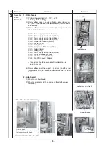
Compre
ss
or lead
Compre
ss
or lead
Inverter
Inverter
a
ss
em
b
ly
a
ss
em
b
ly
Hook
Hook
Ca
s
e thermo
s
tat
Ca
s
e thermo
s
tat
Compre
ss
or lead
Partition plate
Partition plate
Inverter
a
ss
em
b
ly
Inverter
Inverter
a
ss
em
b
ly
a
ss
em
b
ly
Inverter
a
ss
em
b
ly
Hook
Partition plate
Ca
s
e thermo
s
tat
Fan-IPDU
b
oard
Fan-IPDU
b
oard
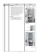
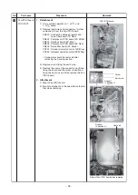
Remove the fan motor lead wire
Remove the fan motor lead wire
from the cord clamp.
from the cord clamp.
Remove the fan motor lead wire
from the cord clamp.
Remove the fan motor lead wire
Remove the fan motor lead wire
from the cord clamp.
from the cord clamp.
Remove the fan motor lead wire
from the cord clamp.
Di
s
charge port
Di
s
charge port
ca
b
inet
ca
b
inet
Di
s
charge port
ca
b
inet
Interface
b
oard
Interface
b
oard
Interface
b
oard
Fan-IPDU
b
oard
C
u
t the
C
u
t the
b
anding
b
and
b
anding
b
and
C
u
t the
b
anding
b
and
C
u
t the
C
u
t the
b
anding
b
and
b
anding
b
and
C
u
t the
b
anding
b
and
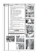
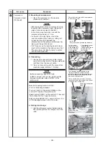
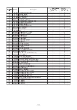
No.
4
Part name
Inverter
a
ss
em
b
ly
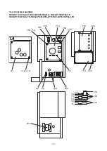
Procedure
1. Detachment
1) Carry o
u
t the operation in 1. of
, 1. of
a
b
ove.
2) Remove the connector
s
connected to the Fan IPDU
b
oard, the connector connected to other component
s
from the control
b
oard
(Interface
b
oard).
CN600 : TS
s
en
s
or (3P: White, t
ub
e: Gray)
CN601 : TE
s
en
s
or (2P: White, t
ub
e: Bl
u
e)
CN602 : TO
s
en
s
or (2P: Yellow, t
ub
e: Black)
CN603 : TD
s
en
s
or (3P: White, t
ub
e: Red)
CN604 : TL
s
en
s
or (2P: White, t
ub
e: White)
CN609 : Ca
s
e thermo
s
tat. (2P: Bl
u
e)
CN690 : High pre
ssu
re
s
witch (3P: Green)
CN700 : 4-way coil (3P: Yellow)
CN710 : PMV coil (6P: White)
• Fan IPDU
b
oard
CN700 : O
u
tdoor
s
lower fan motor (3P: Bl
u
e)
CN750 : O
u
tdoor
s
u
pper fan motor (3P: White)
C
u
t the
b
anding
b
and and remove connector connected
from fan motor to fan motor relay
b
oard.
∗
Remove connector
s
after
u
nlocking ho
us
ing
s
ection
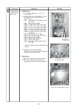
3) Remove the
s
crew (1 po
s
ition) fixing the di
s
charge port
ca
b
inet.
4) C
u
t
bu
ndling
b
and fixing vario
us
lead line
s
to inverter
a
ss
em
b
ly.
5) Remove
s
o
u
nd-in
su
lation plate (
u
pper).
6) Remove terminal cover of compre
ss
or and remove
compre
ss
or lead.
7) P
u
ll
u
p the inverter a
ss
em
b
ly at
u
pper
s
ide to remove
hook of partition plate (rear left part).
2. Attachment
1) Mo
u
nt the inverter a
ss
em
b
ly on the partition plate.
CAUTION
When mo
u
nting the inverter a
ss
em
b
ly on the partitioning
plate, en
su
re proper mo
u
nting of the hook (rear left part)
with partitioning plate.
2) Mo
u
nt the individ
u
al component
s
in the oppo
s
ite
proced
u
re to that d
u
ring detachment.
Remarks
Содержание RAV-GP1101AT8-E
Страница 23: ... 23 4 WIRING DIAGRAM 4 1 Outdoor Unit RAV GP1101AT8 J E TR RAV GP1401AT8 J E TR RAV GP1601AT8 J E TR ...
Страница 103: ... 103 Outdoor Unit RAV GP1401AT8 E RAV GP1401AT8J E RAV GP1401AT8 TR RAV GP1401AT8J TR ...
Страница 105: ... 105 Outdoor Unit RAV GP1601AT8 E RAV GP1601AT8J E RAV GP1601AT8 TR RAV GP1601AT8J TR ...


