


~ 30 ~
GB
~ 30 ~
E
LECTRICAL
W
IRING
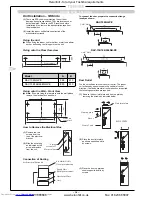
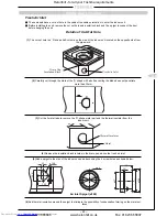
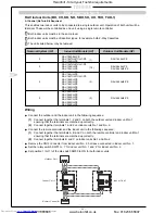
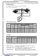
Wiring Between Units
Connect the wires between the units correctly. Errors made in the connections can result in the
unit malfunctioning.
Connect the control wires between the outdoor unit and indoor unit as shown in the figure below:
!
!
Connect the central
remote controller here
(OPTION)
Connect the remote
controller here
(OPTION)
Connect wiring between
indoor and outdoor unit here
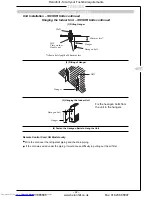
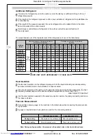
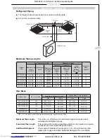
Connecting the Remote Controller —
BH, CH, KH, NH, SBH, SH, TUH, TUH-1, UH only
Any standard 3-core cable operating at 12VAC with a cross-sectional area ranging from 0.3mm
2
to
0.75mm
2
and with a maximum length of 500 metres can be used.
When routing this cable, care should be taken to ensure that it is not in direct contact with mains
cable or routed in duct or conduit containing power cables.
Connect the terminals A, B and C on the remote controller with the terminals A, B and C on the
indoor unit terminal block, ensuring that the terminals are matched up correctly.
Full instructions on the setting and operation of this controller are included in the owner’s manual,
supplied with the remote controller.
!
!
!
!
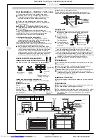
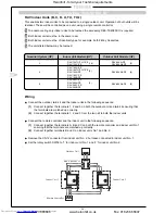
Group Control –
BH, CH, KH, NH, SBH, SH, TUH, TUH-1, UH only
Up to 16 air conditioners can be controlled as a group using a single remote controller. (The
control circuit for each indoor unit originates at the outdoor unit from the incoming phase
connection marked L or L
1
. It is important that on a group system that all the control circuits
throughout the group are derived from the same phase.)
No parts (except for the connecting cable) are required for group control.
Proceed with the power cable connections and with the wiring connections between the indoor
and outdoor units in exactly the same way as for individual air conditioner operation.
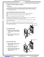
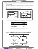
Connect the remote controller and the indoor unit in the following sequence:
1 Connect together the terminals A, B and C on both the remote controller and indoor unit No.1
ensuring that the terminals are matched up correctly;
2 Connect together terminals B and C on indoor units No.1 and No.2;
3 Connect together terminals B and C on indoor units No.2 and No.3;
4 Proceed in the same way to make the necessary connections up to indoor unit No.16;
!
!
!
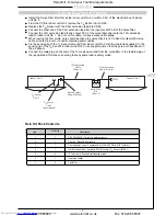
Remote controller
Indoor unit (No.1)
Indoor unit Indoor unit
(No.2 – No.16)
Precautions
Use cables with a cross-sectional area of at
least 0.75mm
2
to connect the indoor units. The
maximum length of 500 metres for the remote
controller cable denotes the maximum length
from the remote controller to the furthest
indoor unit.
!
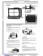
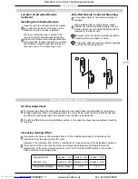
5 Leave the (CN12) connector in unit No.1 but remove
from any further indoor units to prevent malfunction due to miswiring.
6 Set the rotary switch position on each indoor unit to a different number, starting with position 1 for
unit No.1 which is connected to the remote controller. This will also ensure that each unit will start
up at a slightly different time therefore ensuring no increase in start-up current.
(Indoor unit terminal blocks)
Heronhill - for all your Toshiba requirements
Tel: 01823 665660
www.heronhill.co.uk
Fax: 01823 665807


