


~ 11 ~
GB
~ 11 ~
I
NDOOR
U
NIT
L
OCATION
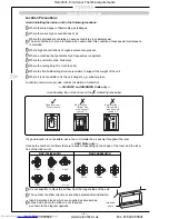
l
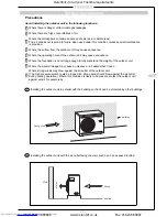
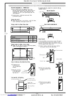
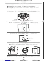
Check the dimensions of the unit illustrated in the following figure:
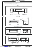
Unit Installation –
BH/B Units
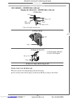
Installing Ø 10 Hanging Bolts (4 pieces)
l
Install the hanging bolts at the intervals shown in the
following figure.
l
Use Ø 10 hanging bolts (to be locally procured).
Ceiling preparation: The actual procedure differs according
to the structure. Consult your builder or whoever was
responsible for the interior of the house/building.
Removal of part of the ceiling plate:
(1) In order to ensure that the ceiling is kept perfectly
horizontal and to prevent the ceiling from vibrating, the
ceiling framework must be reinforced.
(2) Cut and remove part of the ceiling framework.
(3) Reinforce the ends of the ceiling framework where it was
cut and add framework to secure the ends.
l
Some piping and wiring connections must be made in the
ceiling after the unit has been suspended. After selecting where
the unit will be installed, decide on the direction of the piping
connection. If the ceiling is already installed, prepare the
refrigerant pipes, drain pipe, indoor to outdoor unit connection
wiring and the remote control cord at the piping and wiring
connection positions before suspending the indoor unit.
Hanger
bolt
Hanging bolt
Hanging
bolt
Beam
Ceiling
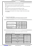
Model (RAV-)
A
B
E
Ø F
Ø G
H
J
K
M
N
264BH
1000
1050
1080
15.9
9.5
252
580
290
2
3
364BH/B, 464BH/B
1350
1400
1430
19.0
9.5
252
930
310
3
4
164BH/B
700
750
780
12.7
6.4
252
280
280
1
2
264B
1000
1050
1080
15.9
9.5
252
580
290
2
3
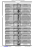
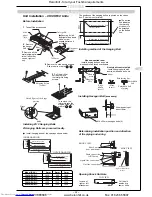
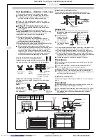
Sliding bracket
Reinforcing
bar
Foundation bolt
(Foundation bolt for
hanging the piping)
Angular bracket
for support
Installation on a wooden structure:
Place a length of wood of the appropriate size across two
beams and install the hanging bolts onto this length of wood.
Installation on a steel frame:
Use the angular
bracket in
the structure
or install
one for support.
Installation on an existing con-
crete slab:
Use hole-in anchors, hole-in plugs
or hole-in bolts for the installation.
Hanging Unit
(1) Raise the unit by using a lift-
ing device, then secure the
hangers to the hanging
bolts. Be sure to fix the nuts
onto both the upper and
under side of the hanger
and the washer (under side
only);
(2) Install the unit horizontally
by using a level. Failure to
do this will cause water
leakages.
Nut
Hanger
Hanging
Bolt
Washer
How to Install the Hanging Bolts
Installation on a newly installed concrete slab:
Use insert brackets or foundation bolts for the installation.
Cross
length of
wood
Knife shaped
bracket
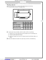
(Gas ø F)
Hanging Bolt Pitch B
Refrigerant Pipe
Connection
Unit Dimension A
Hanging Bolt
4-M10
Provided at site
Nx Ø200
Air Outlet
Drain pipe connection
(inner diameter 32)
(diameter 32 minimal for PVC pipes)
Refrigerant pipe
connection
(liquid ø G)
Hanging Bolt Pitch:565
Unit Dimension:800
J = M x K
(H)
6 x Ø4 holes (Ø160)
Fresh air inlet Ø125
cut-out (other side)
Filter kit
Heronhill - for all your Toshiba requirements
Tel: 01823 665660
www.heronhill.co.uk
Fax: 01823 665807


