• Be sure to disconnect the motor connector CN
31
after shut off the power supply, or it will be a cause of
damage of the motor.
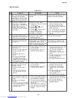
(2) Power is not turned on though Indoor P.C. board is replaced
<Confirmation procedure>
NO
Turn off power supply once, and
5 second later, turn it on again.
Is OPERATION indicator flashing?
Is it possible to turn on
power supply by pushing
[START/STOP] button
on remote controller?
Is voltage
(DC12V or 5V)
indicated on rear of
indoor control
board normal?
Does transmission mark
on remote controller flash
normally,and is its signal
transmitted properly?
Is DC310–340V
supplied between
CN10 1 – 3 ?
Does fan
motor connector
between CN10 1 –
3 short-circuit?
Item by symptoms
Operation
Check Item
Considerable principle cause
Measures
Parts (R04, R05, DB01, C01,
C03, IC01 and T01) are defective.
Remote controller is defective.
Refer to (5) “Troubleshooting
for remote controller”.
Parts of a power supply circuit
defective.
Unit operates normally.
Replace main
P.C. board
Replace fan
motor.
Is fuse (F01)
of indoor control
board blown?
Microcomputer
is defective.
NO
NO
NO
NO
NO
NO
YES
YES
YES
YES
YES
YES
YES
YES
YES
NO
NO
To item of
“Power supply is not turned on”.
Turn on power supply.
Does OPERATION indicator flash?
Is wired correctly to white and
black lead wires of terminal block?
Correct wiring.
( RAS-16 Series )
–
77
–
Rdvised
Содержание RAS-16SAV-E
Страница 19: ... 18 5 WIRING DIAGRAM 5 1 RAS 13SKV E RAS 13SAV E RAS 10SKVR E RAS 10SAVR E RAS 13SKVR E RAS 13SAVR E Revised 1 ...
Страница 20: ...5 2 RAS 16SKV E RAS 16SAV E RAS 16SKVR E RAS 16SAVR E 19 ...
Страница 106: ... 105 R05 L01 C01 CN23 FUSE R04 R01 CN10 J04 IC03 C20 IC01 T01 C03 DB01 RAS 16 Series ...


