background image

2  Troubleshooting Procedures  

2.14 Bluetooth Troubleshooting


PORTEGE M300  Maintenance Manual (960-504) 


2-53 

Procedure 2 

Antennas' Connection Check 

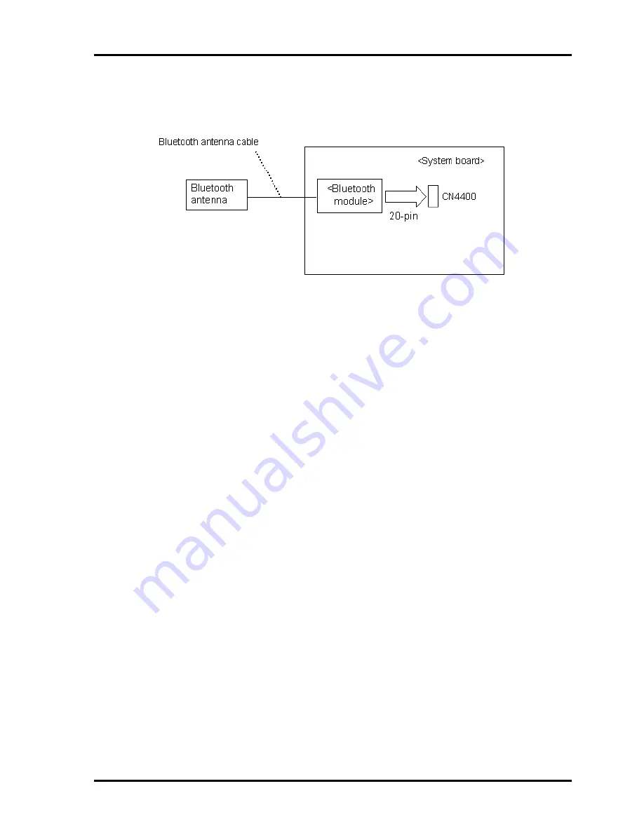
The Bluetooth function-wiring diagram is shown below: 


Any of the connections may be defective. Disassemble the computer following the steps 
described in Chapter 4, 

Replacement Procedures

, and perform the following checks: 


Check 1 

Make sure that the wireless communication switch is “On”. 

If the switch is “Off”, turn it “On”. If the problem still occurs, perform Check 2. 

Check 2 

Make sure that Bluetooth module is firmly connected to the CN4400 on system 
board. If the connector is defective, connect it firmly and perform Procedure 1. If 
the problem still occurs, perform Check 3. 

Check 3 

Make sure that Bluetooth antenna cables is firmly connected to the connectors on 
Bluetooth module. If Bluetooth antenna cable is not connected properly, connect 
them firmly and perform Procedure 1. If the problem still occurs, go to the 
procedure 3. 

Содержание Portege M300

Страница 1: ...Toshiba Personal Computer PORTEGE M300 Maintenance Manual TOSHIBA CORPORATION File Number 960 504 ...

Страница 2: ...als are subject to change without notice Therefore Toshiba assumes no liability for damages incurred directly or indirectly from errors omissions or discrepancies between any succeeding product and this manual Trademarks IBM is a registered trademark and IBM PC is a trademark of International Business Machines Corporation Intel Intel SpeedStep Centrino Pentium and Celeron are trademarks or registe...

Страница 3: ... hazard that could result in bodily injury if the safety instruction is not observed CAUTION Caution indicates the existence of a hazard that could result in property damage if the safety instruction is not observed NOTE Note contains general information that relates to your safe maintenance service Improper repair of the computer may result in safety hazards Toshiba requires service technicians a...

Страница 4: ...nose and resolve FRU problems Chapter 3 Test and Diagnostics describes how to perform test and diagnostic operations for maintenance service Chapter 4 Replacement Procedures describes the removal and replacement of the FRUs Appendices The appendices describe the following Handling the LCD module Board layout Pin assignments Display codes Key layout Wiring diagrams BIOS Rewrite Procedures EC KBC Re...

Страница 5: ...on the keyboard is printed in boldface type Key operation Some operations require you to simultaneously use two or more keys We identify such operations by the key top symbols separated by a plus sign For example Ctrl Pause Break means you must hold down Ctrl and at the same time press Pause Break If three keys are used hold down the first two and at the same time press the third User input Text t...

Страница 6: ... 2 Troubleshooting Procedures 2 1 Troubleshooting 2 1 2 2 Troubleshooting Flowchart 2 3 2 3 Power Supply Troubleshooting 2 7 2 4 System Board Troubleshooting 2 18 2 5 USB FDD Troubleshooting 2 31 2 6 HDD Troubleshooting 2 34 2 7 Keyboard Troubleshooting 2 39 2 8 Touch pad Troubleshooting 2 41 2 9 Display Troubleshooting 2 42 2 10 Optical drive Troubleshooting 2 45 2 11 Modem Troubleshooting 2 46 2...

Страница 7: ... Test 3 25 3 13 Hard Disk Test 3 26 3 14 Real Timer Test 3 29 3 15 NDP Test 3 31 3 16 Expansion Test 3 32 3 17 CD ROM DVD ROM Test 3 34 3 18 Error Code and Error Status Names 3 35 3 19 Hard Disk Test Detail Status 3 38 3 20 Only One Test 3 40 3 21 Head Cleaning 3 48 3 22 Log Utilities 3 49 3 23 Running Test 3 51 3 24 Floppy Disk Drive Utilities 3 52 3 25 System Configuration 3 57 3 26 Wireless LAN...

Страница 8: ... Memory module 4 17 4 6 Keyboard 4 19 4 7 Switch membrane 4 22 4 8 Bluetooth 4 24 4 9 Optical drive 4 25 4 10 Display assembly 4 28 4 11 Speaker 4 35 4 12 Touch pad 4 36 4 13 Wireless LAN card 4 38 4 14 RTC battery 4 39 4 15 LAN jack 4 40 4 16 System board 4 41 4 17 Microphone 4 43 4 18 Fan 4 44 4 19 Cooling fin 4 45 4 20 HDD FPC 4 47 4 21 Modem 4 48 4 22 DC IN jack 4 50 4 23 PC card slot cover 4 ...

Страница 9: ... panel 4 65 4 30 Hinge 4 67 4 31 Fluorescent lamp 4 68 Appendices Appendix A Handling the LCD Module A 1 Appendix B Board Layout B 1 Appendix C Pin Assignments C 1 Appendix D Display Codes D 1 Appendix E Key Layout E 1 Appendix F Wiring Diagrams F 1 Appendix G BIOS Rewrite Procedures G 1 Appendix H EC KBC Rewrite Procedures H 1 Appendix I Reliability I 1 ...

Страница 10: ...x PORTEGE M300 Maintenance Manual 960 504 ...

Страница 11: ...umber 353 Chipset The PORTEGE M300 is equipped with Intel 855GME Montara GM as North Bridge Intel ICH4 M as South Bridge and Texas Instrument PCI7421 as Card Controller Memory One 256MB memory is mounted on the system board One DDR SO DIMM slots is available for installation of DDR333 PC2700 compatible 256 512MB and 1GB memory module HDD 2 5 inch one 30GB 40G 60GB 80GB 100GB HDD is supported USB F...

Страница 12: ...1 Hardware Overview 1 1 Features 1 2 PORTEGE M300 Maintenance Manual 960 504 Touch pad with two buttons is installed as a pointing device ...

Страница 13: ...PORTEGE M300 Button Switch TOSHIBA Assist Button and TOSHIBA Presentation Button are available Also wireless communication switch can turn on off the power of bluetooth and wireless LAN function Batteries The computer has two batteries a rechargeable Lithium Ion main battery pack and RTC battery that backs up the Real Time Clock and CMOS memory Universal Serial Bus USB2 0 Three USB ports are provi...

Страница 14: ...J11 modem jack for connecting to a telephone line Internal LAN The computer is equipped with LAN circuits that support Ethernet LAN 10 megabits per second 10BASE T Fast Ethernet LAN 100 megabits per second 100 BASE TX i LINK IEEE1394 This port enables high speed data transfer directly from external devices such as digital video cameras Wireless LAN Wireless LAN Card can be equipped with mini PCI s...

Страница 15: ...ntenance Manual 960 504 1 5 Sound system The sound system is equipped with the following features Built in stereo speakers Built in monaural microphone Stereo Headphone jack 3 5mm mini headphone jack External microphone jack 3 5mm mini microphone jack ...

Страница 16: ...1 Hardware Overview 1 1 Features 1 6 PORTEGE M300 Maintenance Manual 960 504 The front of the computer is shown in Figure 1 1 Figure 1 1 Front of the computer ...

Страница 17: ...1 1 Features 1 Hardware Overview PORTEGE M300 Maintenance Manual 960 504 1 7 The system unit configuration is shown in Figure 1 2 Figure 1 2 System unit configuration ...

Страница 18: ...rdware Overview 1 2 System Unit Block Diagram 1 8 PORTEGE M300 Maintenance Manual 960 504 1 2 System Unit Block Diagram Figure 1 3 is a block diagram of the system unit Figure 1 3 System unit block diagram ...

Страница 19: ...94V FSB 400MHz L1 cache 64KB 32KB Code 32KB Data L2 cache 512MB Memory One 256MB memory is mounted on the system board One DDR SO DIMM slots is available for installation of DDR333 PC2700 compatible 256 512MB and 1GB memory module Supports DDR333 PC2700 2 5 volt operation 200 pin SO Dual In line Memory Modules SO DIMM North Bridge Intel GMCH M One Intel 855GME is used Features Memory Controller su...

Страница 20: ...upports Plug and Play Supports ACPI Internal PCI IDE Controller USB interface SMBus interface Super I O Interface Audio system SW modem interface 421 ball 31 31mm BGA Package PC Card Controller Texas Instruments PCI7421 One PCI 7421 is used This gate array has the following functions and components PCI interface PCI Revision2 2 CardBus PC Card controller Yenta2 Version2 2 SD MMC card controller SD...

Страница 21: ...47N217 JV Clock Generator ICS made 950812CGLFT RS 232C Driver MAXIM made MAX3243CAI TG074 Audio AMP Matsushita made AN12941A VF AXIS accelerometer STMicro made LIS3L02AQ Internal LAN Controller One Kinnereth 82562ET chip is used Supports 10 100Mbit Ethernet Supports LED and WOL Wireless LAN Card 2 4GHz DSSS OFDM 5 0GHz OFDM wireless LAN card is equipped Conformity with IEEE 802 11b b g or a b g Th...

Страница 22: ...rive that supports 720KB and 1 44MB The FDD is shown in figure 1 4 The specifications for the FDD are listed in Table 1 1 Figure 1 4 USB FDD Table 1 1 USB FDD specifications Items 720KB mode 1 44MB mode FDD part 250K bits second 500K bits second Data transfer rate USB Full speed mode 12M bits second Disk rotation speed 300rpm 360rpm Track density 5 3 track mm 135TPI ...

Страница 23: ... Overview PORTEGE M300 Maintenance Manual 960 504 1 13 1 4 Hard Disk Drive A 30GB 40GB 60GB 80GB 100GB 2 5 inch HDD is supported The HDD is shown in Figure 1 5 and the specification is shown in Table 1 2 and Table 1 3 Figure 1 5 HDD ...

Страница 24: ...epth mm 100 0 Outline dimensions Weight g 95 Standard value Parameter HGST G8BC0001E311 HGST G8BC0001E411 HGST G8BC0001N611 HGST G8BC0001N811 Width mm 69 85 0 25 Height mm 9 5 0 2 Depth mm 100 2 0 25 Outline dimensions Weight g 95 max 102 Standard value Parameter HGST G8BC0001N410 HGST G8BC0001N610 HGST G8BC0001N810 HGST G8BC0001NA10 Width mm 69 85 0 25 Height mm 9 5 0 2 Depth mm 100 2 0 25 Outlin...

Страница 25: ...tra DMA mode Storage density Kbpi 735 Track density Ktpi 88 1 88 8 78 9 Average random seek time read ms 12 Average random seek time write ms 12 Power on to ready sec 4 Specification Parameter HGST G8BC0001E311 HGST G8BC0001E411 HGST G8BC0001N611 HGST G8BC0001N811 Storage size formatted 30GB 40GB 60GB 80GB Speed RPM 4 200 Data transfer speed Mbits s 512 493 Interface transfer rate MB s 100 Ultra D...

Страница 26: ...001N410 HGST G8BC0001N610 HGST G8BC0001N810 HGST G8BC0001NA10 Storage size formatted 40GB 60GB 80GB 100GB Speed RPM 5 400 Data transfer speed Mbits s 493 Interface transfer rate MB s 100 Ultra DMA mode Storage density Kbpi 764 MAX Track density Ktpi 113 2 Average random seek time read ms 12 Average random seek time write ms 14 Power on to ready sec 3 5 ...

Страница 27: ...nce drive that reads DVD at maximum 8 speed and CD at maximum 24 speed The DVD ROM CD R RW drive is shown in Figure 1 6 The dimensions and specifications of the DVD ROM CD R RW drive are described in Table 1 4 Table 1 5 Figure 1 6 DVD ROM CD R RW drive Table 1 4 DVD ROM CD R RW drive outline dimensions Parameter Standard value Maker MATSUSHITA G8CC00025110 Width mm 128 Height mm 12 7 excluding pro...

Страница 28: ... RW 4x CLV High Speed CD RW 4x 8x 10x CLV Ultra Speed CD RW 10x CLV MAX24x CAV Data transfer speed ATAPI interface MB s PIO mode16 6 MB s PIO MODE4 supported DMA mode16 6 MB s Multi word MODE2 supported Ultra DMA mode 33 3 MB s Ultra DMA MODE2 CD ROM 150 Random Access time ms DVD ROM 170 Random Buffer memory 2MB CD CD DA CD ROM CD ROM XA CD R CD RW Photo CD Video CD CD Extra CD CD text Supported d...

Страница 29: ... maximum 8 speed and CD at maximum 24 speed It writes CD at maximum 24 speed The DVD Super Multi drive is shown in Figure 1 7 The dimensions and specifications of the DVD Super Multi drive are described in Table 1 6 Table 1 7 Figure 1 7 DVD Super Multi drive Table 1 6 DVD Super Multi drive outline dimensions Parameter Standard value Maker MATSUSHITA G8CC00026110 MATSUSHITA G8CC00026112 Width mm 12...

Страница 30: ...RW 8x 10x CLV DVD R 1x 2x CLV DVD RW 1x 2x CLV DVD R 2 4x CLV DVD RW 2 4x CLV DVD RAM 2x ZCLV 4 7GB 9 4GB Data transfer speed ATAPI interface MB s PIO mode 16 6 MB s PIO MODE4 supported DMA mode 16 6 MB s Multi ward MODE2 supported Ultra DMA mode 33 3 MB s Ultra DMA MODE2 supported CD ROM 150 Random Access time ms DVD ROM 180 Random Buffer memory 2MB CD CD DA CD ROM CD R CD RW CD ROM XA Photo CD V...

Страница 31: ...RW 8x 10x CLV DVD R 1x 2x CLV DVD RW 1x 2x CLV DVD R 2 4x CLV DVD RW 2 4x CLV DVD RAM 2x ZCLV 4 7GB 9 4GB Data transfer speed ATAPI interface MB s PIO mode 16 6 MB s PIO MODE4 supported DMA mode 16 6 MB s Multi ward MODE2 supported Ultra DMA mode 33 3 MB s Ultra DMA MODE2 supported CD ROM 150 Random Access time ms DVD ROM 180 Random Buffer memory 2MB CD CD DA CD ROM CD R CD RW CD ROM XA Photo CD V...

Страница 32: ...504 1 6 Keyboard A keyboard which consists of 85 86 key is mounted on the system unit The keyboard is connected to the system board and controlled by the keyboard controller Figure 1 8 is a view of the keyboard See Appendix E about a layout of the keyboard Figure 1 8 keyboard ...

Страница 33: ...erter board 1 7 1 LCD Module The LCD module displays in resolution of 1024 H 768 V 16M colors Figure 1 9 shows a view of the LCD module and Table 1 8 lists the specifications Figure 1 9 LCD module Table 1 8 LCD module specifications Specifications Item 12 1 inch XGA G33C00027110 Number of Dots 1 024 W x 768 H Dot spacing mm 0 240 H x 0 240 V Display range mm 245 76 H x 184 32 V ...

Страница 34: ...inverter board supplies a high frequency current to illuminate the LCD module FL Table 1 9 lists the FL inverter board specifications Table 1 9 FL inverter board specifications Specifications Item G71C0002K210 Voltage V 5 0 DC Input Power W 4 0 Voltage V 750 r m s Power W V 3 6W 5VA Output Current mA f 70KHz 4 22 r m s ...

Страница 35: ...connected to the computer 2 Detects DC output and circuit malfunctions 3 Controls the battery icon and DC IN icon 4 Turns the battery charging system on and off and detects a fully charged battery 5 Turns the power supply on and off 6 Provides more accurate detection of a low battery 7 Calculates the remaining battery capacity 8 Controls the transmission of the status signal of the main battery Th...

Страница 36: ... 1 25 Yes No No On board DDR SDRAM VREF 1R5 S1V 1 5 Yes Yes No ICH4 M S3V 3 3 Yes Yes No ICH4 M EC KBC Acceleration sensor M5V 5 0 Yes Yes No ICH4 M Thermal RESET IC Docker PnP ID EEPROM LEDs MCV 5 0 Yes Yes No PSC E5V 5 0 Yes No No PC Card Power USB Power E3V 3 3 Yes No No PCI7421 1394 EEPROM PC CF SD Card Power Mini PCI LAN Power RS232C Driver Receiver MDC FM E3V 3 3 Yes No No SD Card PHY E3V 3 ...

Страница 37: ...1 8 Power Supply 1 Hardware Overview PORTEGE M300 Maintenance Manual 960 504 1 27 32 768KHz generator 1R25 P1V 1 25 No No No DDR SDRAM Termination 1R5 P1V 1 5 No No No GMCH DVO ICH4 M ...

Страница 38: ...sor GMCH ICH4 M SO DIMM SPD HDD FIR Mini PCI FWH Super I O AC97 Codec HP Amp Acceleration sensor P5V 5 0 No No No ICH4 M HDD Mini PCI KB LED PAD LEDs HDD RESET Parallel RGB DDC FL P5V 5 0 No No No FL Inverter DDC P5V 5 0 No No No CRT SND P5V 5 0 No No No Speaker Amp A4R7 P4V 4 7 No No No AC97 Codec Speaker Amp MIC Amp Line IN Line OUT ODD P5V 5 0 No No No ODD ODD RESET PNL P3V 3 3 No No No LCD BT ...

Страница 39: ... specifications Battery name Material Output voltage Capacity G71C0004G110 G71C0004G210 6 Cell 4 700mAh G71C0003W110 Main battery G71C0003W210 Lithium Ion 12 Cell 10 8V 8 800mAh RTC battery P71035009115 Nickel hydrogen 2 4V 16mAh 1 9 1 Main Battery The removable main battery pack is the computer s main power source when the AC adaptor is not attached The main battery maintains the state of the com...

Страница 40: ...able 1 12 Time required for charges of main battery Condition Charging Time 4700mAh About 4 0 to 5 5 hours Normal charge Power on 8800mAh About 6 0 to 9 0 hours 4700mAh About 3 0 hours Quick charge Power off 8800mAh About 4 5 hours Charge is stopped in the following cases 1 The main battery is fully charged 2 The main battery is removed 3 Main battery or AC adapter voltage is abnormal 4 Charging c...

Страница 41: ...r to keep the current date time and other setup information in memory while the computer is turned off Table 1 14 lists the charging time and data preservation period of the RTC battery Table 1 14 RTC battery charging time Condition Time Power ON Lights Power LED About 8 hours Data preservation tome Full charged About 30 days ...

Страница 42: ...y Table 1 15 lists the AC adapter specifications Table 1 15 AC adapter specifications Parameter Specification G71C0001A310 G71C0002S310 G71C0004A210 G71C00049210 Option Power 45W 60W 75W Input voltage 100V to 240V Input frequency 50Hz 60Hz Input voltage 0 6A to1 1A 1 5A or less Output voltage DC 15V Output current 0A to 3 0A 0A to 4 0A 5 0A ...

Страница 43: ...Chapter 2 Troubleshooting Procedures ...

Страница 44: ...2 Troubleshooting Procedures 2 ii PORTEGE M300 Maintenance Manual 960 504 ...

Страница 45: ...xecution Check 2 29 Procedure 4 Replacement Check 2 30 2 5 USB FDD Troubleshooting 2 31 Procedure 1 FDD Head Cleaning Check 2 31 Procedure 2 Diagnostic Test Program Execution Check 2 32 Procedure 3 Connector Check and Replacement Check 2 33 2 6 HDD Troubleshooting 2 34 Procedure 1 Message Check 2 34 Procedure 2 Partition Check 2 35 Procedure 3 Format Check 2 36 Procedure 4 Diagnostic Test Program ...

Страница 46: ...2 Troubleshooting Procedures 2 iv PORTEGE M300 Maintenance Manual 960 504 Procedure 2 Connector and Replacement Check 2 41 ...

Страница 47: ...ram Execution Check 2 46 Procedure 2 Connector Check and Replacement Check 2 46 2 12 LAN Troubleshooting 2 48 Procedure 1 Diagnostic Test Program Execution Check 2 48 Procedure 2 Connector Check and Replacement Check 2 48 2 13 Wireless LAN Troubleshooting 2 49 Procedure 1 Transmitting Receiving Check 2 49 Procedure 2 Antenna Connection Check 2 50 Procedure 3 Replacement Check 2 51 2 14 Bluetooth T...

Страница 48: ...roubleshooting flowchart 2 4 Figure 2 2 A set of tool for debug port test 2 21 Tables Table 2 1 Battery Icon 2 7 Table 2 2 DC IN icon 2 8 Table 2 3 Error code 2 10 Table 2 4 Debug port error status 2 22 Table 2 5 FDD error code and status 2 32 Table 2 6 Hard disk drive error code and status 2 37 ...

Страница 49: ...2 Troubleshooting Procedures PORTEGE M300 Maintenance Manual 960 504 2 vii ...

Страница 50: ...edures are described in Chapter 4 NOTE 1 When replacing the system board make sure to follow the procedures below 1 Execute the subtest03 DMI information save of 3 3 Setting of the hardware configuration in Chapter 3 in order to save DMI data from the old system board to Floppy disk 2 Copy the DMI data to a new system board by executing the subtest04 DMI information recovery and subtest08 System c...

Страница 51: ...anual 960 504 There are following two types of connections in the figure of board and module connection in and after 2 3 Power Supply Troubleshooting 1 Cable connection is described in the figure as line 2 Pin connection is described in the figure as arrow e g Connection of modem ...

Страница 52: ...ermining which troubleshooting procedures to execute Before going through the flowchart steps verify the following Ask him or her to enter the password if a password is registered Verify with the customer that Toshiba Windows is installed on the hard disk Non Windows operating systems can cause the computer to malfunction Make sure all optional equipment is removed from the computer ...

Страница 53: ...2 2 Troubleshooting Flowchart 2 Troubleshooting Procedures 2 4 PORTEGE M300 Maintenance Manual 960 504 Figure 2 1 Troubleshooting flowchart 1 2 ...

Страница 54: ...2 Troubleshooting Procedures 2 2 Troubleshooting Flowchart PORTEGE M300 Maintenance Manual 960 504 2 5 Figure 2 1 Troubleshooting flowchart 2 2 ...

Страница 55: ...m the Keyboard Troubleshooting Procedures in Section 2 7 5 If an error is detected on the Touch pad test in Only One Test perform the Touch pad Troubleshooting Procedures in Section 2 8 6 If an error is detected on the display test perform the Display Troubleshooting Procedures in Section 2 9 7 If an error is detected on the CD ROM DVD ROM test perform the Optical drive Troubleshooting Procedures ...

Страница 56: ...s Battery icon DC IN icon The power supply controller displays the power supply status through the Battery icon and the DC IN icon as listed in Table 2 1 and Table 2 2 below To check the power supply status install a battery pack and connect an AC adapter Table 2 1 Battery Icon Battery icon Power supply status Lights orange Battery is charged and the external DC is input It has no relation with ON...

Страница 57: ...n the DC IN icon blinks and an error code is displayed When the icon is blinking perform the following procedure 1 Remove the battery pack and the AC adapter 2 Re attach the battery pack and the AC adapter If the icon is still blinking after the operation above check the followings Check 1If the DC IN icon blinks orange go to Procedure 2 Check 2If the DC IN icon does not light go to Procedure 3 Ch...

Страница 58: ...ssor detects a malfunction the DC IN iconblinks orange The blink pattern indicates an error as shown below Start Off for 2 seconds Error code 8 bit 1 On for one second 0 On for a half second Interval between data bits Off for a half second The error code begins with the least significant digit Example Error code 12h Error codes are given in hexadecimal format Start ...

Страница 59: ...e hexadecimal error code and compare it to the tables below Table 2 3 Error code Error code Where Error occurs 1 h DC Power AC Adapter 2 h Main battery 3 h Second battery 4 h S3V output 5 h 1R5 C1V output 6 h 1R5 C1V output 7 h PPV output 8 h PTV output 9 h E5V output A h E3V output B h PPV output C h 1R35 P1V output D h 1R25 P1V output E h 2R5 B2V output F h ...

Страница 60: ... 5 A when there is no load 23h Main battery charge current is over 3 10 A when the AC adapter is not directly connected 24h Current sensing IC is not normal when there is no load 25h Main battery charge current is over 0 3 A when the charging is off Second Battery Error code Meaning 30h Over voltage has been sensed Error code 30h is not supported 31h Second battery charge current is over 7 00 A 32...

Страница 61: ... 1R5 C1V voltage is 1 275V or less when the computer is booting up 63h 1R5 C1V voltage is 1 275V or less when the computer is suspended 64h 1R5 C1V voltage is not normal when the computer is shut down CV support 65h 1R5 C1V voltage is 1 275V or less at power on CV support PPV output P63 MUX_CH0 Error code Meaning 70h PPV voltage is over 1 80 V when the computer is powered on off 71h PPV voltage is...

Страница 62: ... less when the computer is booting up A3h E3V voltage is 2 81 V or over when the computer is powered off A4h E3V voltage is 2 81 V or less when the computer is suspended PPV output P63 CH1 Error code Meaning B0h PPV voltage is over 1 80 V when the computer is powered on off B1h PPV voltage is 0 56 V or less when the computer is powered on B2h PPV voltage is 0 56 V or less when the computer is boot...

Страница 63: ...5 B2V voltage is over 3 00 V when the computer is powered on off E1h 2R5 B2V voltage is 2 125 V or less when the computer is powered on E2h 2R5 B2V voltage is 2 125V or less when the computer is booting up E3h 2R5 B2V voltage is 2 125 V or over when the computer is powered off E4h 2R5 B2V voltage is 2 125 V or less when the computer is suspended Check 2 In the case of error code 10h or 12h Make su...

Страница 64: ... outlet If these cables are connected correctly go to Check 2 Check 2 Make sure the DC IN harness is firmly plugged to the connector on the system board If the harness is connected correctly go to Check 3 Check 3 Replace the AC adapter and the AC power cord with new ones If the DC IN icon does not light go to Procedure 5 If the battery icon does not light go to Check 4 Check 4 Make sure the batter...

Страница 65: ... properly installed If the battery is properly installed go to Check 3 Check 3 The battery pack may be completely discharged Wait a few minutes to charge the battery pack while connecting the battery pack and the AC adapter If the battery pack is still not charged go to Check 4 Check 4 The battery s temperature is too high or low Return the temperature to normal operating condition If the battery ...

Страница 66: ...cted Check 1 AC adapter may be faulty Replace the AC adapter with a new one If the problem still occurs perform Check 2 Check 2 DC IN harness may be faulty Replace the DC IN harness with a new one If the problem still occurs perform Check 3 Check 3 System board may be faulty Replace the system board with a new one When AC adapter is not connected When driving with battery pack Check 1 Battery pack...

Страница 67: ... This section describes how to determine if the system board is functioning properly Perform the steps below starting with Procedure 1 and continuing with the other procedures as required Procedure 1 Message Check Procedure 2 Debugging port Check on Boot Mode Procedure 3 Diagnostic Test Program Execution Check Procedure 4 Replacement Check ...

Страница 68: ...he data is lost If you press the F1 key as the message instructs the SETUP screen appears to set the system configuration If any other error message is displayed perform Check 2 a Bad HDD type Check system Then press F1 key b Bad RTC battery Check system Then press F1 key c Bad configuration Check system Then press F1 key d Bad memory size Check system Then press F1 key e Bad time function Check s...

Страница 69: ...is displayed go to the HDD Troubleshooting Procedures If error message 22 is displayed go to the USB FDD Troubleshooting Procedures 1 PIT ERROR 2 MEMORY REFRESH ERROR 3 TIMER CH 2 OUT ERROR 4 CMOS CHECKSUM ERROR 5 CMOS BAD BATTERY ERROR 6 FIRST 64KB MEMORY ERROR 7 FIRST 64KB MEMORY PARITY ERROR 8 VRAM ERROR 9 SYSTEM MEMORY ERROR 10 SYSTEM MEMORY PARITY ERROR 11 EXTENDED MEMORY ERROR 12 EXTENDED ME...

Страница 70: ... set of tool for debug port test The test procedures are follows 1 Connect the debug test cable to the connector CN3400 of the system board For the position of debug port on the system board refer to Appendix B For disassembling to connect the test cable refer to Chapter 4 2 Connect the debug port test cable and RS 232C cross cable to the test board 3 Connect the RS 232C cross cable to the PC that...

Страница 71: ...n of special register and M1535 PIT CH0 initialization for HOLD_ON BIOS rewrite factor flag initialization Check sum check FEFC0000h FEFF7FFFh Transition to protected mode Boot block checksum Program halt when check sum error Checksum other than boot block F001h EC KBC rewrite check BIOS rewrite process when rewrite is requested KBC initialization sequence Send KB Enables command Check F12 key F00...

Страница 72: ...ing of parameters for 2HD 1 44MB Setting of transmission rate Reading of first sector If it is the data of 1 44MB 2HD the media type is definite Setting of parameters for 2DD 720KB Setting of transmission rate Retrieval of CHGBIOSA EXE from the root directory Calculates the directory start header and sector Reading one sector of the root directory Retrieval the entry of CHGBIOSA EXE and CHGFIRMA E...

Страница 73: ...ly when cold booting In the case of CMOS error no resume occurs If resume status code is not set no resume occurs Resume error check ICH4 M Power Failure Error Resume error 7AH SM RAM checksum error Resume error 73H Memory configuration change check Resume error 73H Checksum of system BIOS RAM area Resume error 79H Go go resume process RESUME_MAIN Resume error process Prohibition of all SMI Clears...

Страница 74: ...el 2 Setting of the sound generator frequency to 664Hz Test of PIT channel 1 Check whether the refresh signal works normally in 30 micro s refresh interval Program halt when time out Test of PIT channel 2 Check whether the speaker gate works normally CPU clock measurement Permission of SMI except auto off function Battery discharging current control Dividing procedures for time measuring by IRT Se...

Страница 75: ...Sound initialization PIC initialization PIC test Password Initialization F108h HDD initialization sequence start PCI bus initialization WakeUp factor check F109h Task generation for waiting INIT_PCI completion CMOS data initialization 2 Setting power off Enable Clear of WakeUp factor CPU speed control Panel open close control Serial interrupt control Serial interrupt control Before serial interrup...

Страница 76: ...iting for completion of VGA chip initialization VGA BIOS initialization F111h DISP_LOGO Logo display F112h SYS_MEM_CHECK Conventional memory check F113h EXT_MEM_CHECK Exception check in protected mode F114h CHK_DMA_PAGE DMA Page Register check F117h CHECK _DMAC DMA check F118h INIT_DMAC DMA initialization F119h Password check BOOT_PASSWORD Waiting for completion of INIT_FDD segmentation Waiting fo...

Страница 77: ...r Cancel of NMI Mask TIT check sum Clear of the IRT flag of Runtime side Update of check sum of Runtime side Upgrade check for CPU HDD Prohibition of unused PC cards HW initialization before Boot Waiting for initialization completion Setting of battery save mode Setting of date Waiting for completion of AC Link initialization Update of DMI Wakeup factor Update of SM BIOS structure table PCI device...

Страница 78: ... Test Menu Refer to Chapter 3 Tests and Diagnostics for more information on how to perform these tests System test Memory test Keyboard test Display test Floppy Disk test Printer test Async test Hard Disk test Real Timer test NDP test Expansion test CD ROM DVD ROM test Only One test Wireless LAN test LAN Modem Bluetooth IEEE1394 test Sound test If an error is detected during these tests go to Proc...

Страница 79: ...ollowing the steps described in Chapter 4 Replacement Procedures and perform Check 1 Check 1 Visually check for the following a Cracked or broken connector housing b Damaged connector pins If connectors are properly plugged but there is still a problem go to Check 2 Check 2 The system board may be damaged Replace the system board with a new one following the steps described in Chapter 4 Replacemen...

Страница 80: ...ostic Test Program Execution Check Procedure 3 Connector Check and Replacement Check Procedure 1 FDD Head Cleaning Check FDD head cleaning is one option available in the Diagnostic Program After connecting USB FDD insert the Diagnostics Disk in the floppy disk drive Turn on the computer and run the test And then clean the FDD heads using the cleaning kit If the FDD still does not function properly...

Страница 81: ... 2 5 If any other errors occur while executing the FDD diagnostics test go to Check 1 Table 2 5 FDD error code and status Code Status 01h Bad command 02h Address mark not found 03h Write protected 04h Record not found 06h Media replaced 08h DMA overrun error 09h DMA boundary error 10h CRC error 20h FDC error 40h Seek error 60h FDD not drive 80h Time out error Not ready EEh Write buffer error FFh D...

Страница 82: ...is loose connect firmly and repeat Procedure 2 If the problem still occurs go to Check 2 NOTE When checking the connection be sure to check it with care for the followings 1 Cable can not be disconnected from the connector 2 Cable is connected straight to the connector 3 Cable is connected all the way seated in the connector 4 Cable can not be broken Check 2 USB FDD may be faulty Replace it with a...

Страница 83: ...isk and start the computer Perform the following checks Check 1 Input C and press Enter If you cannot change to drive C go to Check 2 If you can change to drive C go to Procedure 2 Check 2 Input FDISK and press Enter Choose Display Partition Information from the FDISK menu If drive C is listed in the Display Partition Information go to Check 3 If drive C is not listed return to the FDISK menu and ...

Страница 84: ...er 5 seconds this message will disappear Check 2 If either of the following messages appears go to Check 3 If the following messages do not appear perform Check 4 Insert system disk in drive Press any key when ready or Non System disk or disk error Replace and press any key when ready Check 3 Using the SYS command of the MS DOS transfer the system to the HDD If the system is not transferred go to ...

Страница 85: ...f MS DOS For the format by the test program refer to the Chapter 3 Check 1 Format an HDD using MS DOS FORMAT command Type as FORMAT C S U If HDD can not be formatted perform Check 2 Check 2 Using the MS DOS FDISK command set the HDD partition If the partition is not set go to Check 3 If it is set format HDD using MS DOS FORMAT command Check 3 Using the Diagnostic Disk format HDD with a format opti...

Страница 86: ...d statuses are described in Table 2 6 If an error code is not displayed but the problem still occurs go to Procedure 5 Table 2 6 Hard disk drive error code and status Code Status 05 HDD HDC NOT RESET ERROR 07 HDD DRIVE NOT INITIALIZE 09 HDD DMA BOUNDARY ERROR 0B HDD BAD TRACK ERROR BB HDD UNDEFINED ERROR 08 HDD OVERRUN ERROR DRQ ON 01 HDD BAD COMMAND ERROR 02 HDD ADDRESS MARK NOT FOUND 04 HDD RECO...

Страница 87: ... and that HDD FPC is firmly connected to system board If any of the connections are loose reconnect firmly and repeat Procedure 1 If the problem still occurs go to Check 2 Check 2 HDD FPC may be faulty Replace it with a new one following the instructions in Chapter 4 Replacement Procedures and check the operation If the problem still occurs perform Check 3 Check 3 HDD may be faulty Replace it with...

Страница 88: ...Procedure 1 Diagnostic Test Program Execution Check Procedure 2 Connector and Replacement Check Procedure 1 Diagnostic Test Program Execution Check Execute the Keyboard Test DIAGNOSTIC TEST and Pressed key display test ONLY ONE TEST in the Diagnostic Program Refer to Chapter 3 Tests and Diagnostics for more information on how to perform the test program If an error occurs go to Procedure 2 If an e...

Страница 89: ...Procedures and perform the following checks Check 1 Make sure keyboard cable is firmly connected to system board If the connection is loose reconnect firmly and repeat Procedure 1 If the problem still occurs go to Check 2 Check 2 Keyboard may be faulty Replace it with a new one following the instructions in Chapter 4 Replacement Procedures If the problem still occurs perform Check 3 Check 3 System...

Страница 90: ...dure 2 If an error does not occur touch pad is functioning properly Procedure 2 Connector and replacement Check The connection of cable and system board may be defective Otherwise they may be faulty Disassemble the computer following the steps described in Chapter 4 Replacement Procedures and perform the following checks Check 1 Make sure the cable is firmly connected to system board If the connec...

Страница 91: ...he computer s external monitor port then boot the computer The computer automatically detects the external monitor If the external monitor works correctly the internal LCD may be faulty Go to Procedure 3 If the external monitor appears to have the same problem as the internal monitor system board may be faulty Go to Procedure 2 Procedure 2 Diagnostic Test Program Execution Check The Display Test p...

Страница 92: ...d to system board via FL inverter The connections of FL inverter is consist of LCD FL cable and HV cable And fluorescent lamp is connected to FL inverter by HV cable THese cables may be disconnected from system board or FL inverter Disassemble the computer following the steps described in Chapter 4 Replacement Procedures If the connection is loose reconnect firmly and restart the computer If the p...

Страница 93: ...lace fluorescent lamp with a new one following the instructions in Chapter 4 Replacement Procedures and test the display again If the problem still occurs perform Check 2 Check 2 LCD FL cable may be faulty Replace FL LCDcable with a new one following the instructions in Chapter 4 Replacement Procedure and test the display again If the problem still occurs perform Check 3 Check 3 FL inverter may be...

Страница 94: ...pare the tools before the test If any error is detected by the test go to Procedure 2 Procedure 2 Connector Check and Replacement Check The connection of optical drive and system board may be defective Otherwise they may be faulty Disassemble the computer following the steps described in Chapter 4 and perform the following checks Check 1 Make sure optical drive is firmly connected to the connector...

Страница 95: ...Tests and Diagnostics for more information on how to perform the test program If any error is detected perform Procedure 2 Procedure 2 Connector Check and Replacement Check MDC Modem Daughter Card is used as the modem for this computer MDC is connected to system board If modem malfunctions The connection of cable and connector or module may be defective Otherwise they may be faulty Disassemble the...

Страница 96: ... perform Check 3 Check 3 MDC may be faulty Replace it with a new one following the steps in Chapter 4 If the problem still occurs perform Check 4 Check 4 MDC harness may be faulty Replace it with a new one following the instructions in Chapter 4 If the problem still occurs perform Check 5 Check 5 System board may be faulty Replace it with a new one following the instruction in Chapter 4 ...

Страница 97: ... error is detected by the test go to Procedure 2 Procedure 2 Connector Check and Replacement Check The LAN function is embedded on system board If LAN malfunctions its connection is defective or LAN cable and system board may be faulty Check 1 Make sure LAN cable is firmly connected to LAN jack If the problem still occurs perform Check 2 Check 2 LAN cable may be faulty Replace it with a new one If...

Страница 98: ...n Check Procedure 3 Replacement Check Procedure 1 Transmitting Receiving Check Before starting the test make sure the wireless communication switch is set in the ON position Check 1 Execute Wireless LAN test program to check the transmitting receiving function of wireless LAN You will need a second computer that can communicate by wireless LAN Perform the test following the instructions described ...

Страница 99: ...ss communication switch is On If the switch is Off turn it On If the problem still occurs perform Check 2 Check 2 Make sure that wireless LAN card is firmly connected to the CN2200 Mini PCI on system board If the connector is defective connect it firmly and perform Procedure 1 If the problem still occurs perform Check 3 Check 3 Make sure that wireless LAN antenna cables black and white are firmly ...

Страница 100: ... then perform the following checks Check 1 Wireless LAN antenna may be faulty Replace it with a new one following the instructions in Chapter 4 Replacement Procedures If the problem still occurs perform Check 2 Check 2 Wireless LAN card may be faulty Replace it with a new one following the instructions in Chapter 4 Replacement Procedures If the problem still occurs perform Check 3 Check3 System bo...

Страница 101: ...eck Procedure 3 Replacement Check Procedure 1 Transmitting Receiving Check Before starting the test make sure the wireless communication switch is set in the ON position Check 1 Execute Bluetoothtest programto check the transmitting receiving function of Bluetooth You will need a second computer that can communicate by Bluetooth Perform the test following the instructions described in Chapter 3 If...

Страница 102: ...e that the wireless communication switch is On If the switch is Off turn it On If the problem still occurs perform Check 2 Check 2 Make sure that Bluetooth module is firmly connected to the CN4400 on system board If the connector is defective connect it firmly and perform Procedure 1 If the problem still occurs perform Check 3 Check 3 Make sure that Bluetoothantenna cables is firmly connected to t...

Страница 103: ...hen perform the following checks Check 1 Bluetooth antenna may be faulty Replace it with a new one following the instructions in Chapter 4 Replacement Procedures If the problem still occurs perform Check 2 Check 2 Bluetooth module may be faulty Replace it with a new one following the instructions in Chapter 4 Replacement Procedures If the problem still occurs perform Check 3 Check3 System board ma...

Страница 104: ...ctor Check Procedure 3 Replacement Check Procedure 1 Diagnostic Test Program Execution Check Execute the Sound test in Sound Test program disk Refer to Chapter 3 Tests and Diagnostics for more information on how to perform the test program If any error is detected by the test go to Procedure 2 Procedure 2 Connector Check The connection of sound system is shown in the following figure As the connec...

Страница 105: ...it with a new one following the steps in Chapter 4 If the problem still occurs perform Check 5 Check 2 Headphone may be faulty Replace it with a new one following the steps in Chapter 4 If the problem still occurs perform Check 5 Check 3 Internal microphone may be faulty Replace it with a new one following the steps in Chapter 4 If the problem still occurs perform Check 5 Check 4 Speaker may be fa...

Страница 106: ...PORTEGE M300 Maintenance Manual 960 504 3 i Chapter 3 Tests and Diagnostics ...

Страница 107: ...3 ii PORTEGE M300 Maintenance Manual 960 504 ...

Страница 108: ...ogram 3 7 3 3 Setting of the hardware configuration 3 8 3 4 Heatrun Test 3 11 3 5 Subtest Names 3 12 3 6 System Test 3 14 3 7 Memory Test 3 16 3 8 Keyboard Test 3 17 3 9 Display Test 3 18 3 10 Floppy Disk Test 3 21 3 11 Printer Test 3 23 3 12 Async Test 3 25 3 13 Hard Disk Test 3 26 3 14 Real Timer Test 3 29 3 15 NDP Test 3 31 3 16 Expansion Test 3 32 3 17 CD ROM DVD ROM Test 3 34 3 18 Error Code ...

Страница 109: ...figuration 3 57 3 25 1 Function Description 3 57 3 25 2 Operations 3 58 3 26 Wireless LAN Test Program Intel made b 3 59 3 27 Wireless LAN Test Program Intel made b g 3 61 3 28 Wireless LAN Test Program Intel made a b g 3 65 3 29 Wireless LAN Test Program Askey made 3 70 3 30 LAN Modem Bluetooth IEEE1394 Test Program 3 74 3 30 1 LAN test 3 74 3 30 2 Modem test 3 77 3 30 3 Bluetooth test 3 78 3 30 ...

Страница 110: ...PORTEGE M300 Maintenance Manual 960 504 3 v 3 32 1 Function Description 3 94 3 32 2 Accessing the SETUP Program 3 96 ...

Страница 111: ... 1 Subtest names 3 12 Table 3 2 Error codes and error status names 3 35 Table 3 3 Hard disk controller status register contents 3 38 Table 3 4 Error register contents 3 39 Table 3 5 Error message 3 80 Table 3 6 Error code for Bluetooth test BD_ADDR 3 81 Table 3 7 Error code for Bluetooth test BD_ADDR of the DUT 3 85 ...

Страница 112: ...PORTEGE M300 Maintenance Manual 960 504 3 vii ...

Страница 113: ...e computer It is also included in one of Diagnostic Disks The heatrun test is automatic test program which executes the some tests successively NOTE Before starting the diagnostics be sure to follow these steps 1 Check all cables are connected firmly 2 Exit any application and close Windows 3 Check if ALL Device is selected in the item Device Config in SETUP menu After checking the diagnostics be ...

Страница 114: ...disk for maintenance and Sound test disk for maintenance A formatted working disk Floppy disk test A cleaning kit to clean the floppy disk drive heads Head Cleaning An external CRT monitor supporting monitor ID Expansion test A CD test media TOSHIBA CD ROM TEST DISK or ABEX TEST CD ROM Sound test A DVD test media DVD ROM TEST DISK TSD 1 Sound test A music CD Sound test A CD RW test media CD ROM DV...

Страница 115: ...rams Initial configuration Region write DMI information save DMI information recovery System configuration display E2PROM test MAC GUID DMI You will need the following equipment to perform some of the programs The Diagnostics Disk Main T D 3 1 3 Heatrun test program The heatrun test starts automatically after the selection You will need the following equipment to perform this program The Diagnosti...

Страница 116: ...air Heatrun T D Enter a choice 1 To start the Diagnostics menu T D press 1 and Enter To start the H W initial information setting tool press 2 and Enter To start the Heatrun test press 3 and Enter NOTE When replacing the system board be sure to execute the following procedures 1 Before replacing the system board execute subtest03 DMI information save in 3 3 Setting of the hardware configuration in...

Страница 117: ...the DIAGNOSTIC TEST MENU press the Esc key If a test program is in progress press Ctrl Break to exit the test program If a test program is in progress press Ctrl C to stop the test program Set the highlight bar to 1 and press Enter The following DIAGNOSTIC TEST MENU will appear TOSHIBA personal computer Common DIAGNOSTICS version X XX c copyright TOSHIBA Corp 20XX DIAGNOSTIC TEST MENU 1 SYSTEM TES...

Страница 118: ...3 2 Executing the Diagnostic Test 3 Tests and Diagnostics 3 6 PORTEGE M300 Maintenance Manual 960 504 ...

Страница 119: ...t end Ctrl C key stop SUB TEST XX PASS COUNT XXXXX ERROR COUNT XXXXX WRITE DATA XX READ DATA XX ADDRESS XXXXXX STATUS XXX SUB TEST MENU 01 ROM checksum 02 Fan ON OFF 03 Geyserville 04 Quick charge 05 DMI read 99 Exit to DIAGNOSTIC TEST MENU NOTE The menu displayed by your computer may be slightly different from the one shown above Select the desired subtest number from the subtest menu and press E...

Страница 120: ...tes the test program and exits to the subtest menu 2 Continues the test 3 Restarts the test from the error Selecting NO keeps the test running even if an error is found When an error occurred the error status is displayed and one error is added to the error counter Table 3 1 in section 3 5 describes the function of each test on the subtest menu Table 3 2 in section 3 18 describes the error codes a...

Страница 121: ... Test PORTEGE M300 Maintenance Manual 960 504 3 9 For more details on this test refer to the section 3 3 3 2 3 Heatrun test program Heatrun test starts executing the same subtest as 3 23 RUNNING TEST For more details on this test refer to the section 3 4 ...

Страница 122: ...f the microcode Setting of the EHSS Inputting and writing of DMI information When the DMI information is displayed the following messages appear in order Input each information If you do not replace the PCB the DMI information should not be changed 1 Enter Model Name is displayed Input the computer s model name and press Enter e g PORTEGE 2 Enter Version Number is displayed Input the computer s ve...

Страница 123: ... automatically Press any key to continue Subtest 02 Region write This subtest executes the setting of the region code for DVD drive based on the destination of the machine When the region code is already written test ends without setting The following message appears in the display after setting the region code Press any key to return to the H W initial information setting tool menu It completed P...

Страница 124: ...covery is done the saved UUID data is not written This is one of tools to copy the DMI information to a new PCB after replacing This subtest writes all the DMI data in the floppy disk into the new PCB Subtest 08 System configuration display This subtest displays the information of the system configuration Confirm the contents and press Enter For more details on the system configuration information...

Страница 125: ...NG TEST are executed successively For more details on the procedure and test content refer to RUNNING TEST When the heatrun test ends following message appears in the display HEATRUN TEST END Press any key to continue Press any key and return to the startup menu NOTE The test result Errorlog txt is stored in the floppy disk The result is displayed in the same way as 3 22 LOG UTILITIES For more det...

Страница 126: ...N OFF Geyserville Quick charge DMI read 2 MEMORY 01 02 03 04 05 Conventional memory Protected Mode Protected Mode cache off Cache memory on off Stress 3 KEYBOARD 01 Pressed key code display 4 DISPLAY 01 02 03 04 05 06 07 VRAM read write for VGA Gradation for VGA Gradation for LCD Gradation Mode test for VGA All dot on off for LCD H pattern display LCD Brightness 5 FLOPPY DISK 01 02 03 04 05 Sequen...

Страница 127: ...ceive Wrap around board 8 HARD DISK 01 02 03 04 05 06 07 08 09 Sequential read Address uniqueness Random address data Cross talk peak shift Partial Read Write specified address Read specified address Sequential write W R C specified address 9 REAL TIMER 01 02 03 Real time Backup memory Real time carry 10 NDP 01 NDP test 11 EXPANSION 01 03 PCMCIA wrap around Not supported RGB monitor ID 13 CD ROM D...

Страница 128: ... force with Fan ON OFF commands The following message will appear Fan number select 1 FAN 1 CPU 2 FAN 2 GPU 0 FAN 1 2 To check the CPU fan press 1 and Enter To check the GPU fan press 2 and Enter To check both CPU fan and GPU fan press 0 and Enter The following message will appear Test Fan Revolution 0000RPM start Make sure the fan does not rotate then press Enter The following message will appear...

Страница 129: ...Charge This subtest checks the status for the quick charge Subtest 05 DMI read This subtest displays the information in the Flash ROM in the following format DMI Data Display Ver X XX Model Name XXXXXXXXXXX Version Number XXXXXXXXXXXX Serial Number XXXXXXXX Model Number XXXXXX XXXXX UUID Number XXXXXXXXXXXXXXXXXXXXXXXXXXXXXXXX Press Enter to EXIT To exit this subtest and return to the SYSTEM test ...

Страница 130: ...e This subtest writes constant data and address data from 1MB to maximum MB and reads the new data and compares the result with the original data Subtest 03 Protected Mode Cache off This subtest executes the same way as the subtest02 with the cache off Subtest 04 Cache Memory To test the cache memory a pass through write read comparison of 5Ah data is run repeatedly to the test area 7000 Program s...

Страница 131: ...1 Pressed key code display When a key is pressed the scan code character code and key top name are displayed on the screen in the format shown below The Ins Lock Caps Lock Num Lock Scroll Lock Alt Ctrl Left Shift and Right Shift keys are displayed in reverse screen mode when pressed The scan codes character codes and key top names are shown in Appendix D KEYBOARD TEST IN PROGRESS 302000 Scan code ...

Страница 132: ... is read and compared to the original data Subtest 02 Gradation for VGA This subtest displays four colors red green blue and white from left to right across the screen from black to maximum brightness The display below appears on the screen when this subtest is executed To exit this subtest and return to the DISPLAY TEST menu press Enter Subtest 03 Gradation for LCD This subtest displays bands of ...

Страница 133: ...M Mode 114 800 600 64K Mode 115 800 600 16M Mode 117 1024 768 64K Mode 118 1024 768 16M The display below appears on the screen when this subtest is executed Display example Mode 12 To exit this subtest and return to the DISPLAY TEST menu press Enter after displaying the Mode 118 Subtest 05 All dot on off for LCD This subtest displays an all white screen then an all black screen The display change...

Страница 134: ...HHHHHHHHHHHHHHHHHHHHHHH HHHHHHHHHHHHHHHHHHHHHHHHHHHHHHHHHHHHHHHHHHHHHHHHHH HHHHHHHHHHHHHHHHHHHHHHHHHHHHHHHHHHHHHHHHHHHHHHHHHH HHHHHHHHHHHHHHHHHHHHHHHHHHHHHHHHHHHHHHHHHHHHHHHHHH HHHHHHHHHHHHHHHHHHHHHHHHHHHHHHHHHHHHHHHHHHHHHHHHHH HHHHHHHHHHHHHHHHHHHHHHHHHHHHHHHHHHHHHHHHHHHHHHHHHH HHHHHHHHHHHHHHHHHHHHHHHHHHHHHHHHHHHHHHHHHHHHHHHHHH HHHHHHHHHHHHHHHHHHHHHHHHHHHHHHHHHHHHHHHHHHHHHHHHHH To exit this subtes...

Страница 135: ...ype and test start truck will be displayed successively Answer each question with an appropriate response to execute the test 1 The following message will appear Select the media mode and start track to be tested then press Enter Test start track Enter 0 dd 00 79 2 The Floppy Disk test contains five subtests that test the FDD The floppy disk test menu will appear after you select FDD test paramete...

Страница 136: ...nly Track No Head No Subtest 01 Sequential read This subtest performs a Cyclic Redundancy Check CRC that continuously reads all the tracks track 0 to 39 0 to 79 on a floppy disk Subtest 02 Sequential read write This subtest continuously writes data pattern B5ADADh to all the tracks track 0 to 39 0 to 79 on a floppy disk The data is then read and compared to the original data Subtest 03 Random addr...

Страница 137: ... IBM compatible printer must be connected to the system to execute this test Also printer port wraparound connector must be connected The following message will appear after selecting the subtest 01 to 03 of the printer test channel 1 XXXXh channel 2 XXXXh channel 3 XXXXh Select the channel number 1 3 The printer I O port address is specified by the XXXXh number The computer supports three printer...

Страница 138: ...sized print Double strike print All characters print This subtest prints the various print types shown below Subtest 03 Wraparound NOTE To execute this subtest a printer wraparound connector must be connected to the computer s printer port This subtest checks the output and bi directional modes of the data control and status lines through the parallel port wraparound connector 34M741986G01 Both ou...

Страница 139: ... point send NOTE To execute subtests 01 and 02 each computer must have access to the other computer s infrared port This subtest sends 20h through 7Eh data to the receive side then receives the sent data and compares it to the original data through the FIR SIR port Subtest 02 FIR SIR Point to point receive This subtest is used with subtest 01 described above This subtest receives the data from the...

Страница 140: ...form the back up create back up disks as described below Check to see if the Microsoft Create System Disks Tools MSCSD EXE still exists in the System Tools Folder This tool can be used only once If it exists use it to back up the pre installed software then use the Backup utility in the System Tools folder to back up the entire disk including the user s files Refer to the operating system instruct...

Страница 141: ...e XX XX XX Enter new date PRESS ENTER KEY TO EXIT TEST 2 If the current date is not correct input the correct date at the Enter new date prompt and press Enter 3 The date is updated and the following messages will appear Current date XX XX XXXX Current time XX XX XX Enter new time PRESS ENTER KEY TO EXIT TEST 4 If the current time is not correct input the correct time in 24 hour format To enter pr...

Страница 142: ...3 14 Real Timer Test 3 Tests and Diagnostics 3 30 PORTEGE M300 Maintenance Manual 960 504 Then the subtest reads and compares this data with the original data ...

Страница 143: ...e and time are erased This subtest checks the real time clock increments Make sure the date and time are displayed in the following format Current date 12 31 1999 Current time 23 59 58 The real time increments are automatically executed and the following is displayed Current date 01 01 2000 Current time 00 00 00 PRESS Enter KEY TO EXIT TEST To exit the test press Enter ...

Страница 144: ...nce Manual 960 504 3 15 NDP Test To execute the NDP test select 10 from the DIAGNOSTICS TEST MENU press Enter and follow the directions on the screen Subtest 01 NDP This test checks the following functions of NDP Control word Status word Bus Addition Multiplication ...

Страница 145: ...r is required This subtest checks the following signal line of the PC card slot Address line REG CE 1 CE 2 line Data line Speaker line Wait line BSY BVD1 line This subtest is executed in the following order Sub Address Good Bad Contents 01 00001 00001 nn nn xx xx Address line REG CE 1 CE 2 nn A0 90 80 00 02 00002 ww rr Data line ww write data rr read data 03 00003 Speaker line 04 00004 40 80 xx Wa...

Страница 146: ...or with monitor ID function is required Connect the external monitor to the PC for the test of ID acquisition The judgment of acquisition is based on the panel data In simultaneous display mode or internal display mode in which the panel data is acquired this subtest will fail Therefore make sure only the external display is selected when executing this subtest ...

Страница 147: ...EST CD ROM TCDR 702 and DVD ROM TEST DISK TSD 1 For the subtest 04 use a CD RW media on the market Subtest 01 Sequential read This subtest is a sequential reading of one block units 2K bytes of all the logical addresses Subtest 02 Read specified address This subtest reads one block data from a specified address Subtest 03 Random address data This subtest reads one block data and multi block data f...

Страница 148: ...T ROM SENSING ERROR 1st Batt ROM SENSING ERROR 2nd Batt ROM THORMISTOR ERROR 1 ROM THORMISTOR ERROR 2 ROM THORMISTOR ERROR 3 Memory 01 02 DD RAM PARITY ERROR RAM PROTECTED MODE NO CHANGE RAM CACHE MEMORY ERROR Keyboard FE FD F0 F1 F2 F3 F4 F5 F6 F7 F8 F9 FA EF ED USB GET DESCR ERROR FIRST USB SET ADDRESS ERROR HUB GET DESCR ERROR Top 8B HUB GET DESCR ERROR Whole HUB SET CONFIGURATION ERROR HUB GET...

Страница 149: ...TIME OUT PRT FAULT PRT SELECT LINE PRT OUT OF PAPER PRT POWER OFF PRT BUSY LINE ASYNC 01 02 04 08 10 20 40 80 88 05 06 RS232C DTR ON TIME OUT RS232C CTS ON TIME OUT RS232C RX READY TIME OUT RS232C TX FULL TIME OUT RS232C PARITY ERROR RS232C FRAMING ERROR RS232C OVERRUN ERROR RS232C LINE STATUS ERROR RS232C MODEM STATUS ERROR SIR TIME OUT ERROR FIR TIME OUT ERROR HDD 05 07 09 0B BB 08 01 02 04 10 2...

Страница 150: ...SOR NDP CONTROL WORD ERROR NDP STATUS WORD ERROR NDP BUS ERROR NDP ADDITION ERROR NDP MULTIPLAY ERROR EXPANSION C1 C3 C4 C5 C6 C7 C8 CB CC CE CF ADDRESS LINE ERROR CE 1 LINE ERROR CE 2 LINE ERROR DATA LINE ERROR WAIT LINE ERROR BSY LINE ERROR BVD1 LINE ERROR ZV Port ERROR NO PCMCIA CARD TYPE ERROR ZV_CONT ERROR CD ROM DVD ROM 01 02 03 04 05 06 09 11 20 40 80 90 B0 BAD COMMAND ILLEGAL LENGTH UNIT A...

Страница 151: ...ays the HDC error register The contents of the HDC status register and error register are listed in Tables 3 3 and 3 4 Table 3 3 Hard disk controller status register contents Bit Name Description 7 BSY Busy 0 HDC is ready 1 HDC is busy 6 DRY Drive ready 0 Hard disk drive is not ready to accept any command 1 Hard disk drive is ready 5 DWF Drive write fault 0 DWF error is not detected 1 Write fault ...

Страница 152: ... 6 UNC Uncorrectable 0 There is no uncorrectable data error 1 Uncorrectable data error has been detected 5 Not used 4 IDN Identification 0 Not used 1 There is no ID field in the requested sector 3 Not used 2 ABT Abort 0 Not used 1 Illegal command error or command abort 1 TK0 Track 0 0 The hard disk found track 0 during a recalibrate command 1 The hard disk could not find track 0 during a recalibra...

Страница 153: ...el 3 20 2 Operations Select test 2 from the DIAGNOSTIC MENU and press Enter The following menu appears in the display Only One Test Menu XXXXXXXXX 1 Pressed Key Display 2 Touch Pad 3 Kill Switch 4 USB 5 LED 6 Acceleration sensor 9 Common Test Press test number 1 6 9 Input the subtest number you want to test and press Enter To return to the DIAGNOSTIC TEST menu select 9 and press Enter ...

Страница 154: ...s subtest the keyboard layout is drawn on the display as shown below When any key is pressed the corresponding key on the screen changes to the key character that was pressed Holding a key down enables the auto repeat function which causes the key s display character to blink Press Del Enter to end the test IF TEST OK Press Dell Enter key ...

Страница 155: ...s the response from the touch pad and touch pad switch When moving your finger on the touch pad towards the upper left the POINTING display changes according to the following illustration If a touch pad switch is pressed the BUTTONS displays appear on the right side one by one The parameters appear above the BUTTONS 1 or 2 corresponding to the pressed touch pad switch highlights To end this subtes...

Страница 156: ...splay KILL SWITCH ON Slide the switch to ON position Then the following message appears in the display KILL SWITCH OFF After Sliding the switch to OFF position the screen returns to the Only One Test menu automatically Subtest 04 USB NOTE When executing this subtest USB test module and USB cable must be connected This subtest checks if USB ports work properly The following menu appears in the disp...

Страница 157: ...pears in the display in order Follow the instructions in the display to execute the test HDD Access LED test Confirm the LED of HDD status blinks properly Press any key and following message appears in the display Caps Num Overlay BT W LAN LED test 1 Press Caps Lock key Caps on off 2 Press Fn F10 key Arrow on off 3 Press Fn F11 key Num on off 4 Slide BT W LAN switch L R on off Confirm correspondin...

Страница 158: ... is executed on the following condition 1 Flat desk with vertical plane to get the stability of machine 2 Prevent the machine from shake or shock The figure below shows the name and position of each side Figure 3 1 Name and positions of each side Vertical plane Flat desk Set the machine against the vertical plane with the Front upward Right side right Left side left Back Front Top heaven surface E...

Страница 159: ...lishes in the upper direction Press Enter key Set the machine against the vertical plane on the flat desk with the right side of machine upward Then press Enter to detect the data on this setting of machine The following message appears in the display The front establishes in the upper direction Press Enter key Set the machine against the vertical plane on the flat desk with the front of machine u...

Страница 160: ...ual 960 504 When a defective is found during the each check above the following message appears in the display The test is halted at the point when the defective is found Setting ERROR Press Enter key Press Enter and return to the Only One Test menu Then execute the test again ...

Страница 161: ...his program 3 21 2 Operations 1 Selecting test 4 from the DIAGNOSTIC MENU and pressing Enter displays the following messages DIAGNOSTICS FLOPPY DISK HEAD CLEANING VX XX Mount cleaning disk s on drive s Press any key when ready 2 Remove the Diagnostics Disk from the FDD then insert the cleaning disk and press Enter 3 When the cleaning start message appears the FDD head cleaning has begun 4 The disp...

Страница 162: ...in RAM This function can store data on a floppy disk or output the data to a printer or the display The error information is displayed in the following order 1 Error count CNT 2 Test name Subtest number TS No 3 Pass count PASS 4 Error status STS 5 FDD HDD or memory address ADDR 6 Write data WD 7 Read data RD 8 HDC status HSTS 9 Error status name ERROR STATUS NAME If the power switch is turned off ...

Страница 163: ... displayed on the screen can be manipulated by the following number keys The 1 key scrolls the display to the next page The 2 key scrolls the display to the previous page The 3 key returns to the Diagnostic Menu The 4 key erases all error log information in RAM The 5 key outputs the error log information to a printer The 6 key reads the log information from a floppy disk The 7 key writes the log i...

Страница 164: ...py disk drives connected to the computer for the FDD test 3 23 2 Operations 1 Select 6 from the Diagnostic Menu and press Enter the following messages for selectable tests will appear in the display in order FDD write read test Y N Printer wrap around test Y N Serial wrap around test Y N CD ROM DVD ROM test Y N 2 To execute the test press Y and Enter To cancel the test press N and Enter If you sel...

Страница 165: ...shiba MS DOS FORMAT command This program can format a floppy disk in the following formats a 2DD Double sided double density double track 96 135 TPI MFM mode 512 bytes 9 sectors track b 2HD Double sided high density double track 96 135 TPI MFM mode 512 bytes 18 sectors track 2 COPY This program copies data from a source floppy disk to a target floppy disk 3 DUMP This program displays the contents ...

Страница 166: ...ssage Type select 0 2DD 3 2HD c Select a media drive type number and press Enter A message similar to the one below will be displayed Warning Disk data will be destroyed Insert work disk into drive A Press any key when ready d Remove the Diagnostics Disk from the FDD insert the work disk and press any key The following message will be displayed when the FDD format is executed FDD TYPE TRACK XXX FD...

Страница 167: ...arted FDD TYPE TRACK XXX FDD TYPE HEAD X FDD TYPE SECTOR XX Copy start track head XXX X d The following message will appear Insert target disk into drive A Press any key when ready e Remove the source disk from the FDD then insert a formatted work disk and press any key The following message will appear and start copying to the target disk track head XXX X f When the amount of data is too large to...

Страница 168: ...sage will appear Select a media mode 2HD media mode 1 1 20MB 2 1 44MB 3 1 23MB e The following message will appear Insert source disk into drive A Press any key when ready f Insert a source disk and press any key and the following message will appear Max address Track XXXX Head XX Sector XX Track number g Set the track number head number and sector number you want to dump The system will access th...

Страница 169: ... the dump select 3 Press number key 1 up 2 down 3 end l The following message will appear Selecting 2 returns to the FDD UTILITIES MENU Another dump 1 Yes 2 No 5 HDD ID READ program Selecting HDD ID displays the following HDD ID configuration HDD ID Read VX XX Drive 1 Drive 2 Model No XXXXXXX YYYYYYY Press Enter to return to the FDD UTILITIES MENU ...

Страница 170: ...it of the STATUS number indicates the drive being tested and the last two digits indicate the error status code as explained in table 3 2 of the section 3 18 Subtest 01 Sequential read This subtest is a sequential reading of all the tracks on the HDD starting at track 0 When all the tracks on the HDD have been read the test starts at the maximum track and reads the tracks on the HDD sequentially b...

Страница 171: ...6DB 6 cylinder D25044 7 cylinder Subtest 05 Partial Read This subtest reads 1GB data which is in minimum middle and maximum address of the HDD area Subtest 06 Write specified address This subtest writes specified data to a specified cylinder and head on the HDD Subtest 07 Read specified address This subtest reads data which has been written to a specified cylinder and head on the HDD Subtest 08 Se...

Страница 172: ...2nd ID 4 Boot ROM version 5 EC KBC version 6 PS Microprocessor version 7 SVP parameter version Panel Manufacture code Product code 8 Microcode revision Processor number 9 Total Memory Size Conventional memory 10 Battery code 11 HWSC 12 FSB Voltage 13 The number of printer ports 14 The number of ASYNC ports 15 Math co processors 16 Floppy Disk Drive Track Head Sector 17 Hard Disk Drive Sector Drive...

Страница 173: ...m Version VX XX SVP Par Version VX XX Panel XXXXXXXXX Manu XXXX Prod XXXX Microcode Revision VX XX Processor XXXh Total Memory Size XXXXXXMB Conventional Memory XXXKB Battery Code XXXXXXXXXXXX HWSC XXXXXXX FSB XXXXXMHz Voltage XEh X Printer Adapter LPT1 XXXX LPT2 XXXX LPT3 XXXX X ASYNC Adapter COM1 XXXX COM2 XXXX COM3 XXXX X Math CO Processor X Floppy Disk Drive s Track XX Head XX Sector XX X Hard...

Страница 174: ...s Check 2 Communication test Connection Communication test for MAIN and AUX antenna To start the Wireless LAN test program follow the steps below NOTE Before starting the wireless LAN test make sure the Wireless Communication Switch is turned on Release the write protection of the floppy disk for the test Setting the responder machine Connect the responder machine to the access point with a cross ...

Страница 175: ...f an error is detected during the connection communication test for MAIN AUX NG message appears in the display After pressing any key following message appears in the display and finishes the test Main Antenna Test NG When a defective is detected during the connection communication test for MAIN AUX following typical cause is considered Connection of wireless LAN card Connection of wireless LAN an...

Страница 176: ...ile pressing U The following menu appears in the display Intel Calexico 11b g Card Maintenance test Menu 1 SKU check of Module 2 MAC Address Check 3 Antenna Check communication test of 11b mode 4 Communication test of 11g mode 5 All the tests of Calexico 11g Card SKU MAC Check 11b g communication test SELECT TEST No 1 5 To execute the subtest input the subtest number and press Enter Subtest01 SKU ...

Страница 177: ...This subtest displays the MAC address Selecting this subtest following message will appear in the display MAC XXXXXXXXXXXX MAC Address Check OK Press any key and return to the test menu If a defective is found during the test following message will appear in the display ERROR MAC all 0 MAC XXXXXXXXXXXX MAC Address Check NG Press any key and return to the test menu When a defective is detected in t...

Страница 178: ...1b and 802 11g with a cross cable and turn on the access points Insert the floppy disk containing the wireless LAN test program into the FDD of the responder machine and turn on the responder machine This subtest checks the connection and communication of wireless LAN antenna of Calexico 802 11b mode After finishing the test OK message will appear in the display Press any key and return to the tes...

Страница 179: ...s any key and following message will appear in the display 11g Communication Test NG Press any key and return to the test menu When a defective is detected in the test following typical cause is considered Connection of wireless LAN card Connection of wireless LAN antenna cable Main Condition of wireless LAN communication Interference obstruction Defective wireless LAN card Checking the connection...

Страница 180: ...into the Floppy Disk Drive Turn on the power while pressing U The following menu appears in the display Intel Calexico2 11a g Maintenance T D Menu 1 SKU check of Module 2 MAC Address Check 3 Antenna Check communication test of 11b mode 4 Communication test of 11a mode 5 Communication test of 11g mode 6 All the tests of Calexico2 11a g Card SKU MAC Check 11a b g communication test SELECT TEST No 1 ...

Страница 181: ...3 28 Wireless LAN Test Program Intel made a b g 3 Tests and Diagnostics 3 66 PORTEGE M300 Maintenance Manual 960 504 Press any key and return to the test menu ...

Страница 182: ...g typical cause is considered Connection of wireless LAN card Using a wrong wireless LAN card Using unspecified card Defective wireless LAN card Checking the connection execute the subtest again Subtest02 MAC Address Check This subtest displays the MAC address Selecting this subtest following message will appear in the display MAC XXXXXXXXXXXX MAC Address Check OK Press any key and return to the t...

Страница 183: ...efore executing wireless LAN communication test The wireless communication LED lights orange Release the write protection of floppy disk for the test Setting the responder machine Connect the responder machine to the access points for 802 11a 802 11b and 802 11g with a cross cable and turn on the access points Insert the floppy disk containing the wireless LAN test program into the FDD of the resp...

Страница 184: ... the communication of wireless LAN antenna of Calexico 802 11a mode After finishing the test OK message will appear in the display Press any key and return to the test menu When a defective is found during the test NG message will appear in the display Press any key and following message will appear in the display 11a Communication Test NG Press any key and return to the test menu When a defective...

Страница 185: ...For more details on procedure and contens of this subtest refer to Subtest04 Communication test of 11a mode Subtest06 All the tests of Calexico 11a b g Card This subtest checks SKU information MAC address of Calexico 802 11a b g card antenna connection and communication test of Calexico 802 11b card and communication test of Calexico 802 11a and Calexico 802 11g The test stops at when a defective ...

Страница 186: ...range Release the write protection of floppy disk for the test Setting the responder machine To execute subtest 03 07 responder machine with wireless LAN communication function Atheros made is required To set the responder machine follow the procedures below 1 Insert the test program disk to the FDD of responder machine and turn on the power 2 Start the program for responder machine automatically ...

Страница 187: ...e SKU MAC Check 11a b g communication test SELECT TEST No 1 7 Subtest01 SKU check of module This subtest displays SKU informationon the wireless LAN card installed Selecting this subtest following message will appear in the display Confirm if the right information on the wireless LAN card is described Module Atheros MB44ag RoW G code G36C00010310 Press any key and return to the test menu When a de...

Страница 188: ...address data Checking the connection execute the subtest again Subtest03 Communication test of 11a mode MB44ag This subtest checks the connection and communication of wireless LAN antenna of Atheros 802 11a mode Check the packet throughput and RSSI and compare them with the standard After finishing the test OK message will appear in the display Press any key and return to the test menu When a defe...

Страница 189: ...he contents refer to subtest 03 Subtest05 Communication test of 11g mode MB44ag MB43g This subtest checks the connection and communication of wireless LAN antenna of Atheros 802 11g mode For more details on the contents refer to subtest 03 Subtest06 All the tests of MB43g Module This subtest checks SKU information MAC address connection and communication of wireless LAN antenna of Atheros 802 11b ...

Страница 190: ...e power The following message will appear Microsoft Windows XX Startup Menu 1 LAN 2 Modem 3 Bluetooth 4 IEEE1394 Enter a choice Press the number you want to test and press Enter NOTE It is impossible to go back to startup menu once you choose the test Therefore LAN Modem Bluetooth IEEE1394 test can not be executed successively 3 30 1 LAN test To execute LAN test press 1 and Enter The following mes...

Страница 191: ... chip The following message will appear LAN transmit receive test COMPLETED Repeat count 00000 Error count 00000 LOOPBACK TEST 100Mbps Auto negotiation TxRx Test Destination Address xxxxxxxxxxxx Source Address xxxxxxxxxxxx 100Base TX Full Duplex TRANSMIT RECEIVE NOTE The menu displayed by your computer may be slightly different from the one shown above If a defective is found NG message will appea...

Страница 192: ...f mini PCI I F by the loopback test in the chip Select 2 to execute and press Enter The following message will appear Testing adaptor hit ESC to abort External Loopback Test PASSED Testing completed Loopback Test Complete 1000Base Auto negotiation TxRx Test CE Test Complete NOTE The menu displayed by your computer may be slightly different from the one shown above If a defective is found NG messag...

Страница 193: ...em test press 2 and Enter Following message will appear Modem loopback test ICHx MDC Test Program with Modem Sound Line Test Version X X Scorpio Modem Initialize OK Digital Loopback Test OK RJ11 Connector Check LED Operator s Check NOTE The menu displayed by your computer may be slightly different from the one shown above RJ11 Connection Check LED Operator s Check LED test will be executed and the...

Страница 194: ...orm this test Insert a floppy disk containing the test program into the target machine and turn on the target machine The following Bluetooth test menu will appear Bluetooth sub system test program VX XX 1 BD_ADDR check 3 Communications test DUT mode T communications test TEST mode Press test number 1 3 T _ Press 1 or 3 key to perform the corresponding subtest To quit the Bluetooth test program ej...

Страница 195: ...nter The following message will appear Bluetooth Subsystem T D for PCSE BD_ADDR VerX XX Copyright C by TOSHIBA Co Initializing When the machine has passed the test it displays BD_ADDR If BD_ADDR has no problem the following message is displayed Bluetooth Subsystem T D for PCSE BD_ADDR VerX XX Copyright C by TOSHIBA Co My BD_ADDR XXXXXXXXXXXX h PPPPPP A SSSSS SSSSS P P A A S S S S P P A A S S PPPPP...

Страница 196: ...ooth Subsystem T D for PCSE BD_ADDR VerX XX Copyright C by TOSHIBA Co My BD_ADDR XXXXXXXXXXXX h FFFFFF A III L F A A I L F A A I L FFFFFF A A I L F AAAAAAA I L F A A I L F A A III LLLLLLL Table 3 5 Error message Message Contents Invalid BD_ADDR all 00 0x000000000000 Invalid BD_ADDR all FF 0xFFFFFFFFFFFF Invalid BD_ADDR bit0 1 bit40 1b Invalid BD_ADDR bit1 1 bit41 1b Invalid BD_ADDR define in the f...

Страница 197: ...nnection already exists 0x0c Command Disallowed 0x0d Host Rejected due to limited resources 0x0e Host Rejected due to security reasons 0x0f Host Rejected due to remote device is only a personal device 0x10 Host Timeout 0x11 Unsupported Feature or Parameter Value 0x12 Invalid HCI Command Parameters 0x13 Other End Terminated Connection Used Ended Connection 0x14 Other End Terminated Connection Low R...

Страница 198: ...ecification of the Bluetooth System in detail Subtest03 Communication test DUT mode This subtest checks the Bluetooth communication functions Preparing the tester machine for the Bluetooth test program Insert a floppy disk containing the test program into the tester machine and turn on the tester machine The Bluetooth test menu will appear Press 3 to select the test and press Enter in the target m...

Страница 199: ...Then press Space to start the Bluetooth communication test When the machine has passed the test it displays BD_ADDR of the DUT If the connection with the tester is completed the progress bar stops The following message is shown Bluetooth Subsystem T D for PCSE CS Air VerX XX Copyright C by TOSHIBA Co DUT BD_ADDR of the DUT XXXXXXXXXXXXX h CCCC OOO M M PPPPPP L EEEEEE TTTTTTT EEEEEEE DDDDD C C O O ...

Страница 200: ...or Code Bluetooth Subsystem T D for PCSE CS Air VerX XX Copyright C by TOSHIBA Co DUT BD_ADDR of the DUT XXXXXXXXXXXXX h III N N CCCC OOO M M PPPPPP L EEEEEE TTTTTTT EEEEEEE I NN N C C O O MM MM P P L E T E I N N N C O O M M M M P P L E T E I N N N C O O M M M PPPPPP L EEEEEE T EEEEEEE I N N N C O O M M P L E T E I N NN C C O O M M P L E T E III N N CCCC OOO M M P LLLLLLL EEEEEE T EEEEEEE Testing ...

Страница 201: ... ACL Connection already exists 0x0c Command Disallowed 0x0d Host Rejected due to limited resources 0x0e Host Rejected due to security reasons 0x0f Host Rejected due to remote device is only a personal device 0x10 Host Timeout 0x11 Unsupported Feature or Parameter Value 0x12 Invalid HCI Command Parameters 0x13 Other End Terminated Connection Used Ended Connection 0x14 Other End Terminated Connectio...

Страница 202: ...code Meaning 0x20 Unsupported LMP Parameter Value 0x21 Role Change Not Allowed 0x22 LMP Response Timeout 0x23 LMP Error Transaction Collision 0x24 LMP PDU Not Allowed 0x25 Not Exist 0x26 Not Exist 0x27 Not Exist 0x28 Not Exist 0x29 Not Exist 0x2a Not Exist 0x2b Not Exist 0x2c Not Exist 0x2d Not Exist 0x2e Not Exist 0x2f Not Exist See the Specification of the Bluetooth System in detail ...

Страница 203: ...st number 1 3 To execute the TEST select the test number you want to execute and press Enter Subtest01 Transmit Receive test NOTE Before executing subtest 01 be sure to execute subtest 02 in the responder machine This program checks the data transporting between responder machine and target machine and compare them with the original data through the IEEE1394 cable Subtest02 Responder set This prog...

Страница 204: ...d turn on the power The following message will appear WSS Sound blaster pro Diagnostics program 1 Sound Standard 2 Sound Legacy 3 CD Sound Standard 4 CD Sound Legacy It outputs at the speaker and lineout Press test number 1 4 Input the test number and press Enter 3 31 1 Sound Standard test To execute the Sound Standard test press 1 and Enter The following menu will appear in the display ICH4 M AD1...

Страница 205: ...en this subtest is selected the following message will appear Recording play test And the following message will appear DOS 4GW Protected Mode Run time Version X XX Copyright c Tenberry Software Inc XXXX After this message appears display stops briefly In this timing sound is recorded from internal microphone After the recording is completed the computer plays back the sound recorded after the fol...

Страница 206: ...a can be measured as a sine wave When the subtest is executed the sine wave is played while expanding sine wave from 16KB to 64KB The display returns to the Sound Standard test menu after the test ends Subtest03 Line IN recording play This subtest executes the same test as the subtest01 by recorded sound from the different port Line in port For more details on the subtest refer to the subtest01 Mi...

Страница 207: ... CD on the market refer to 2 Audio CD 1 Test media Toshiba made test media CD DVD TEST IN PROGRESS XXXXXXXX xxxxxxx DIAGNOSTIC TEST VX XX Ctrl Break test end Ctrl C key stop SUB TEST XX PASS COUNT XXXXX ERROR COUNT XXXXX WRITE DATA XX READ DATA XX ADDRESS XXXXXX STATUS XXX 01 Japanese Narration 02 English Narration 03 Test Tone A 100Hz 20Hz 04 Test Tone B 400Hz 3KHz L R Drive 0 ATAPI status 00 Com...

Страница 208: ... procedure refer to the subtest01 Subtest03 Test Tone A Caution Before starting subtest03 be sure to set the sound at proper volume This subtest plays sine wave while changing its table from 100Hz to 20Hz Return to the CD Sound Standard menu after the test ends Subtest 04 Test Tone B This subtest plays sine wave while changing its table from 400Hz to 3KHz and also changing the channel from left sp...

Страница 209: ...0 Command XX Block address XXXXXXXX Block length XXXXXXXX Final Block address XXXXXXXXX Select the track number you want to test and press Enter twice The following message appears in the display and selected track is played Play start CD sound Press any key play stop After pressing any key the music stops and the display returns to the selection menu of the track number NOTE When the CD ROM test ...

Страница 210: ...ow 1 Memory 2 System Date Time 3 Battery 4 Password 5 HDD Password a HDD b HDD Password mode c User Password d Mater Password 6 Boot Priority a Boot Priority b Network Boot Protocol 7 Display a Power On Display b LCD Display Stretch 8 Others a Power up Mode b CPU Cache c Level 2 Cache d Dynamic CPU Frequency Mode e Auto Power On f Panel power On Off g Performance Battery Life Setting 9 Configurati...

Страница 211: ...tenance Manual 960 504 3 95 a Built in HDD b CD ROM 12 PCI Bus 13 Peripheral a Internal Pointing Device b External keyboard Fn c Parallel Port Mode d Hard Disk Mode 14 LEGACY EMULATION a USB KB Mouse Legacy Emulation b USB FDD Legacy Emulation 15 PCI LAN ...

Страница 212: ...0 504 3 32 2 Accessing the SETUP Program Selecting 0 from the DIAGNOSTICS MENU and pressing Enter displays the followings NOTE 1 This item is displayed only when Pentium model is used for CPU 2 This item is displayed only when Resume is set as Power up mode in OTHERS menu box ...

Страница 213: ... requires the system to reboot the following message is displayed Are you sure Y N The changes you made will cause the system to reboot 2 To make other changes press N Repeat the steps above 3 To accept the changes press Y NOTE You can press Esc to quit at any time without saving changes SETUP asks you to confirm that you do not want to save your changes When SETUP is displayed at the next time th...

Страница 214: ...omatically calculated by the computer You cannot change this value 2 System Date Time Sets the date and time System Date Sets date System Time Sets time 3 Battery This option is used to select Full Power Low Poweror User Setting of the battery save mode When you select the battery save mode the followings will appear Full Power The following shows full power settings Low Power The following shows ...

Страница 215: ...mode Display Auto Off Use this option to disable or set the duration of the display automatic power off function This function causes the computer to turn the LCD panel s illumination off if you make no entry including no operation of a mouse or touch pad for the set period of time Disabled Disables display automatic power off xx Min Automatically turns off the power to the LCD panel s illuminatio...

Страница 216: ...CPU becomes too hot the processing speed is lowered If the temperature is still too high the fan turns on When the CPU temperature falls to a normal range the fan is turned off and the processing speed is increased NOTE Too hot condition may cause defect on the CPU When the hot condition continues the power is automatically turned off in resume mode 4 Password This option sets or resets the user p...

Страница 217: ...details refer to the User s Manual 6 Boot Priority a Boot Priority Use this option to set the priority for booting of the computer and the priority for the HDD for booting FDD HDD CD ROM LAN The computer looks for bootable files in the following order FDD HDD CD ROM 1 and LAN HDD CD ROM LAN FDD The computer looks for bootable files in the following order HDD CD ROM LAN and FDD FDD CD ROM LAN HDD T...

Страница 218: ...does not appear on the display you are using after starting in Standby or Hibernation pressing Fn F5 Pressing Fn F5 changes the display setting as follows in order the internal LCD the external CRT both the internal LCD and the external CRT When an external CRT display which does not support SVGA mode is connected and LCD AnalogRGB is selected the external display is not displayed b LCD Display St...

Страница 219: ... CPU of the computer is Celeron M this option is not displayed Dynamically Switchable Enables Pentium M processor featuring Intel SpeedStep technology Default Always High Disables Pentium M processor featuring Intel SpeedStep technology and always runs the processor at its maximum speed Always Low Disables Pentium M processor featuring Intel SpeedStep technology and always runs the processor at it...

Страница 220: ...ction to turn on the power automatically by the call from the administrator It can be set to Enabled only when Built in LAN is set to Enabled To activate this function use the AC adapter NOTE 1 Do not remove the AC adaptor and battery pack at the same time when you use this feature If you do so data saved by the resume function will be lost You must also reset this option 2 If you have set a passw...

Страница 221: ...ode 1 20V Core Voltage 9 Configuration This option lets you set the device configuration All Devices BIOS sets all devices Setup by OS Initializes devices which is needed to load an operating system Operating system initializes other devices NOTE 1 When using installed OS selecting Setup by OS is recommended 2 When executing test programs be sure to select ALL Device And after the test end select ...

Страница 222: ...ddress COM1 4 3F8H Default COM2 3 2F8H COM3 4 3E8H COM3 5 3E8H COM3 7 3E8H COM4 3 2E8H COM4 5 2E8H COM4 7 2E8H Not Used Disables port b Parallel This option sets the interrupt request level and I O port base address for the parallel port When the parallel port mode is set to Std Bi direct the options are as follows LPT setting Interrupt level I O address LPT 1 7 378H LPT 2 5 278H LPT 3 7 3BCH Not ...

Страница 223: ...only and cannot be changed Built in HDD This cannot be changed CD ROM This cannot be changed This is not displayed when a drive is not built in 12 PCI Bus This option displays the interrupt level for the Card Bus in the computer It is for information only and cannot be changed PCI BUS IRQ10 IRQ11 13 Peripheral Use this option to select the peripheral s mode a Internal Pointing Device This option e...

Страница 224: ...tem by pressing Ctrl Alt Del c Parallel Port Mode Use this option to set information of Parallel Port Mode ECP Sets the port mode to Extended Capabilities Port ECP For most printers the port should be set to ECP Default Std Bi Direct Sets the bi directional setting This setting should be used with some other parallel devices NOTE When using Windows the setting of Toshiba HW setup is enabled and th...

Страница 225: ...abled Enables LEGACY support Default USB keyboard USB mouse are available without the driver Disabled Disables LEGACY support b USB FDD Legacy Emulation This option sets the Legacy support condition of the USB floppy disk drive When a computer is FDD built in model this option is not displayed Enabled Enables LEGACY support Default USB floppy disk is available without the driver Disabled Disables ...

Страница 226: ...3 32 SETUP 3 Tests and Diagnostics 3 110 PORTEGE M300 Maintenance Manual 960 504 ...

Страница 227: ...Chapter 4 Replacement Procedures ...

Страница 228: ...4 Replacement Procedures 4 ii PORTEGE M300 Maintenance Manual 960 504 ...

Страница 229: ...Keyboard 4 19 4 7 Switch membrane 4 22 4 8 Bluetooth 4 24 4 9 Optical drive 4 25 4 10 Display assembly 4 28 4 11 Speaker 4 35 4 12 Touch pad 4 36 4 13 Wireless LAN card 4 38 4 14 RTC battery 4 39 4 15 LAN jack 4 40 4 16 System board 4 41 4 17 Microphone 4 43 4 18 Fan 4 44 4 19 Cooling fin 4 45 4 20 HDD FPC 4 47 4 21 Modem 4 48 4 22 DC IN jack 4 50 4 23 PC card slot cover 4 51 4 24 Display latch 4 ...

Страница 230: ...ing the dummy card 4 13 Figure 4 6 Inserting a CF card 4 13 Figure 4 7 Removing the HDD assembly 4 14 Figure 4 8 Removing the HDD 4 15 Figure 4 9 Removing a memory module 4 17 Figure 4 10 Removing the screw fixing keyboard 4 19 Figure 4 11 Removing the speaker cover 4 20 Figure 4 12 Removing the keyboard 4 20 Figure 4 13 Removing the switch membrane 4 22 Figure 4 14 Removing a bluetooth module 4 2...

Страница 231: ... Applying silicon grease 4 46 Figure 4 33 Removing the HDD FPC 4 47 Figure 4 34 Removing the MDC 4 48 Figure 4 35 Removing the modem jack 4 49 Figure 4 36 Removing the DC IN jack 4 50 Figure 4 37 Removing the PC card slot cover 4 51 Figure 4 38 Removing the LED panel 4 53 Figure 4 39 Disassembling the display latch assembly 4 53 Figure 4 40 Removing the battery lock battery latch 4 55 Figure 4 41 ...

Страница 232: ...4 Replacement Procedures 4 vi PORTEGE M300 Maintenance Manual 960 504 ...

Страница 233: ... be removed in order to remove others Always start by removing the battery pack next optional items such as the optional PC card and optional SD card then follow the line on the chart to determine which FRU you must remove next in order to repair the one you think is causing the computer to operate improperly Refer to the example at the bottom of the page How to See the Chart An example of referri...

Страница 234: ...d from an AC power source Remove any metal jewelry or accessories such as necklaces bracelets or rings in order to reduce the risk of electric shock Never work with wet or damp hands 3 Be careful of edges and corners as these may cut CAUTION 1 When you change a component be sure the replacement component meets the required specifications Never use foreign parts to avoid any risk of damage to the c...

Страница 235: ...ecessary diagnostics tests described in this manual 5 Do not perform any operations that are not necessary and use only the described procedures for disassembling and installing FRUs in the computer 6 After removing parts from the computer place them in a safe place away from the computer so they will not be damaged and will not interfere with your work 7 You will remove and replace many screws wh...

Страница 236: ...ressure plate is fully lifted when you insert the cable Coaxial cables should be disconnected with an antenna coaxial disconnector Standard pin connectors are used with all other cables These connectors can be connected and disconnected by simply pulling them apart or pushing them together Assembly Procedures After you have disassembled the computer and fixed or repaired the problem that was causi...

Страница 237: ...r use of these devices will increase the success rate of your repairs and lower the cost for damaged or destroyed parts The following equipment is necessary to disassemble and reassemble the computer One M1 4 point size 0 Phillips screwdriver to remove and replace screws One M2 point size 0 Phillips screwdriver to remove and replace screws One M2 5 M3 point size 1 Phillips screwdriver to remove an...

Страница 238: ...r damage if screws or components come loose NOTE Toshiba recommends that you use an electric screwdriver for quick and easy operations M1 4 1 4mm 0 078 N m 0 8 kgf cm M2 0 2 0mm 0 167 N m 1 7 kgf cm M2 5 2 5mm 0 294 N m 3 0 kgf cm M3 0 3 0mm 0 549 N m 5 6 kgf cm NOTE The computer contains several flat head screws These screws have less contact area with the screwdriver so be careful to press firml...

Страница 239: ...imal places such as 2 5 mm or 2 8 mm Marking of Screws on the Computer Body To make maintenance of the computer easier markings of the kinds of the screws including the types and lengths of the screws are indicated on the computer body Kind of screws Symbol BIND screw B FLAT HEAD screw F SUPER FLAT HEAD screw S TAPPING screw T Other screws U Unique screws STUD etc Examples 6 mm BIND screw B6 12 mm...

Страница 240: ...ot scratch break twist or bend the battery pack 1 Turn off the computer 2 Disconnect the AC cable and other external devices from the computer 3 Turn the computer face down 4 Release the battery lock by sliding the lock toward the arrow direction 5 While sliding the battery release latch pull out the battery pack to the arrow direction Figure 4 1 Removing the Battery pack NOTE Dispose of the used ...

Страница 241: ...de if not properly replaced used handled or disposed of For environmental reasons collect the spent battery packs Use only batteries recommended by Toshiba as replacements NOTE Check the battery s terminals visually If they are dirty wipe them clean with a dry cloth 1 Turn off the computer 2 Disconnect the AC cable and other external devices from the computer 3 Push the battery pack into the batte...

Страница 242: ...entation and your operating system documentation for proper procedures and precautions 1 Push the eject button It will pop out when you release it Then press once more the eject button to eject a PC card 2 Grasp a PC card and pull it out Figure 4 2 Removing a PC card Installing a PC card To install a PC card follow the steps below and refer to figure 4 2 1 Make sure the eject button does not stick...

Страница 243: ...efore you remove a SD card refer to the card s documentation and to your operating system documentation for proper procedures and precautions 1 Push a SD card It will pop out partly when you release so pull out the card Figure 4 3 Removing a SD card Installing a SD Card To install a SD card follow the steps below and refer to figure 4 3 1 Insert a SD card and press it until it is securely connecte...

Страница 244: ... and refer to figure 4 4 CAUTION Before you remove a CF card refer to the card s documentation and your operating system documentation for proper procedures and precautions 1 Push the eject button It will pop out when you release it Then press once more the eject button to eject a CF card 2 Grasp a CF card and pull it out Figure 4 4 Removing a CF card CF card Eject button ...

Страница 245: ...d follow the steps below and refer to figure 4 5 and 4 6 1 Push the eject button It will pop out when you release it Then press once more the eject button to eject the dummy card Figure 4 5 Removing the dummy card 2 Insert a CF card and press it until it is securely connected Figure 4 6 Inserting a CF card Dummy card Eject button CF card ...

Страница 246: ...t press the HDD from the top and bottom surface Pressing HDD may causes data and device destruction 1 Turn the computer upside down 2 Loosen the following screw with e ring and remove the HDD slot cover 3 Lift up the HDD assembly from screw hole side 4 Disconnect the HDD assembly carefully from the connector of the HDD FPC Figure 4 7 Removing the HDD assembly HDD slot cover Screw e ring HDD assemb...

Страница 247: ... Remove the following screws and slide out the HDD from the HDD bracket M3 0 4 0S FLAT HEAD screw 4 NOTE When removing the HDD bracket be sure to remove the screws in the reverse order of the number marked on the holder 4 3 2 1 Figure 4 8 Removing the HDD HDD cushion rubber HDD cushion rubber M3 0x4 0S FLAT BIND M3 0x4 0S FLAT BIND HDD bracket HDD ...

Страница 248: ...lling the HDD bracket be sure to secure the screws in the order of the number marked on the holder 1 2 3 4 2 Cover the HDD cushion rubbers to the both sides of HDD assembly 3 Connect the HDD assembly to the connector of the HDD FPC 4 Seat the HDD assembly in the slot of the computer NOTE When installing the HDD assembly to the slot make sure that the printed character UP on the HDD cushion rubber ...

Страница 249: ... may cause memory access problems Never press hard or bend the memory module Removing a memory module To remove a memory module confirm that the computer is in boot mode Then perform the following procedures and refer to figure 4 9 1 Turn the computer upside down 2 Loosen the screw with e ring and remove the memory slot cover 3 Remove the memory slot cover 4 Open the left and right latches and rem...

Страница 250: ...d press it to connect firmly CAUTION The power must be turned off when you insert a memory module Inserting a memory module with the power on might damage the module or the computer itself Never press hard or bend a memory module 2 Install the memory slot coverand secure it with the screw with e ring 3 When the power of the computer is turned on the computer checks automatically the memory size Co...

Страница 251: ...key top may drop 1 Remove the following screwon the bottom M2 0 6 0B BIND screw 1 Figure 4 10 Removing the screw fixing keyboard 2 Turn the computer face up and open the display 3 Lifting up the speaker cover S from the slit side and remove it 4 Slide the speaker cover L toward the arrow direction and remove it 5 Remove the following screws securing the keyboard M2 0 3 0S S THIN FLAT BIND screw 2 ...

Страница 252: ...rest 7 Peel off the cover tape sticking over the slit for keyboard flexible cable 8 Turning up the cover sheet disconnect the keyboard flexible cable from the connector CN3230 on the system board 9 Pull out the keyboard flexible cable through the slit and remove the keyboard Slit Speaker cover L Speaker cover s M2 0x3 0S S THIN FLAT BIND Cover tape M2 0x3 0S S THIN FLAT BIND or M2 0x4 0B LH STICK ...

Страница 253: ... cover tape over the slit of cover sheet CAUTION Cover tape can not be reused Be sure to use a new cover tape when replacing 3 Turn the keyboard face up and put it on the computer Make sure that there is no gap between the keyboard and the computer 4 Secure the keyboard with the following screws CAUTION Be sure to screw the LH STICK in the left side if the LH STICK is used for the computer when se...

Страница 254: ...re that speaker cable and wireless LAN antenna cables are not come out from the guide And also be careful not to catch the cables between cover assembly and speaker cover L 6 Install the speaker cover S to the computer 7 Turn the computer upside down and secure the keyboard with the following screwon the bottom M2 0 6 0B BIND screw 1 ...

Страница 255: ...igures 4 13 1 Remove the following screwand remove the switch cover M2 0 3 0S S THIN FLAT BIND screw 1 2 Disconnect the switch membrane from the connector CN3270 on the system board 3 Remove the following screws and remove the switch membrane M2 0 3 0S S THIN FLAT BIND screw 2 Figure 4 13 Removing the switch membrane M2 0x3 0S S THIN FLAT BIND Switch cover Switch membrane CN3270 M2 0x3 0S S THIN F...

Страница 256: ...d secure it with the following screws M2 0 3 0S S THIN FLAT BIND screw 2 2 Connect the switch membrane to the connector CN3270 on the system board CAUTION When connecting the switch membrane be careful not to connect it slantwise and be sure to lock the connector 3 Install the switch coverand secure it with the following screw M2 0 3 0S S THIN FLAT BIND screw 1 CAUTION When installing the switch c...

Страница 257: ...sconnect the bluetooth antenna cable from a bluetooth module Figure 4 14 Removing a bluetooth module Installing a Bluetooth To install a bluetooth follow the steps below and refer to figures 4 14 1 Connect the bluetooth antenna cable to the connector on a bluetooth module 2 Connect the bluetooth flat cable to both a bluetooth module and the connector CN4400 on the system board 3 Install a bluetoot...

Страница 258: ...steps below and refer to figures 4 15 and 4 16 1 Turn over the computer and remove the following screws securing an optical drive assembly M2 5 10 0B FLAT BIND screw 1 M2 0 4 0B BIND screw 1 2 Push out an optical drive assembly by pressing it from the slot and remove it Figure 4 15 Removing an optical drive assembly M2 5x4 0B BIND Optical drive M2 5x10 0B FLAT BIND Slot ...

Страница 259: ...d remove it from an optical drive assembly Unique screw Stepping screw 2 4 Remove the following screw securing the side bracket and remove it from an optical drive assembly M2 0 3 0S S THIN FLAT BIND screw 1 Figure 4 16 Removing the brackets Stepping screw Rear bracket Side bracket M2 0x3 0S S THIN FLAT BIND Fitting this dent to the side bracket ...

Страница 260: ... FLAT BIND screw 1 2 Fitting the dent to the side bracket install the rear bracket to an optical drive assembly and secure it with the following screws Unique screw Stepping screw 2 3 Insert an optical drive assembly into the optical drive slot carefully CAUTION When inserting an optical drive be sure to turn the computer face up Also be careful not to insert the drive upside down 4 Turn over the ...

Страница 261: ...splay assembly To remove the display assembly follow the steps below and refer to figures 4 17 to 4 21 1 Close the display and turn the computer face down 2 Remove the following screws on the bottom M2 0 6 0B BIND screw 9 Described 6 in the figure M2 0 4 0B BIND screw 1 Described 4 in the figure Figure 4 17 Removing the screws bottom 6 6 6 6 6 6 6 4 6 6 ...

Страница 262: ...he inverter harness form the connector CN8812 on the system board 7 Disconnect the LAN harness from the connector CN4100 on the system board 8 Disconnect the speaker cable from the connector CN6180 on the system board 9 Disconnect the touch pad cable from the connector CN3240 on the system board Figure 4 18 Removing the screws and cables LAN harness Connected to CN4100 Inverter harness Connected t...

Страница 263: ... glass tape 1 and pull out the bluetooth antenna cable from the guide of cover assembly 11 Turn up the insulators 1 and pull out the wireless LAN antenna cables from the guide of cover assembly Figure 4 19 Removing the antenna cables Insulator 1 Glass tape 1 Bluetooth antenna cable Wireless LAN antenna cable ...

Страница 264: ...ollowing screws securing the hinges and remove the hinges M2 5x8 0B FLAT BIND screw 2 14 Part the display assembly from the base assembly and put it apart with antenna cables connected between both assemblies Figure 4 20 Removing the display assembly Display assembly M2 5x8 0B FLAT BIND with Locktight Hinge cap M2 5x8 0B FLAT BIND M2 5x8 0B FLAT BIND with Locktight Hinge M2 5x8 0B FLAT BIND Hinge ...

Страница 265: ...ables from the wireless LAN card CAUTION When turning up the insulator 2 be careful not to break the SD card slot cover 17 Pull out the wireless LAN antenna cables from the slot of cover assembly 18 Pull out the LAN harness from the slot of cover assembly 19 Part the cover assembly from the base assembly Figure 4 21 Removing the cover assembly LAN harness Cover assembly Insulator 2 Glass tape 2 Wi...

Страница 266: ...ables are not caught in the CF card slot lever 2 When sticking the insulator 2 be careful not to break the SD card slot 3 Secure the wireless LAN antenna cables with the glass tape 2 4 Passing the LAN harness through the slot of cover assembly install the cover assembly to the base assembly 5 Install the display assembly to the base assembly and secure the hinges with the following screws M2 5x8 0...

Страница 267: ...de 13 Arrange the bluetooth antenna cable along the guide of base assembly and secure all antenna cables with glass tape 1 CAUTION When arranging the bluetooth antenna cable make sure bluetoooth antenna cable is not come out from the guide 14 Secure the cover assembly and GND cable with the following screw M2 0x6 0B BIND screw 1 NOTE Be sure to secure the GND cable with the caulked side upward 15 ...

Страница 268: ...rom the slot of cover assembly 2 Peeling off the insulators pull out the speaker cables from the guide of cover assembly Figure 4 22 Removing the speaker Installing the speaker To install the speaker follow the steps below and refer to figures 4 22 1 Install the speaker to the slot of cover assembly 2 Arrange the speaker cable along the guide and secure them with insulators Speaker Insulator Speak...

Страница 269: ...23 and 4 24 1 Peel off the adhered portion of cover sheet and remove the cover sheet from the cover assembly Figure 4 23 Peeling off the cover sheet 2 Remove the pad coverwhile releasing the latches 3 Remove the following screws securing the touch pad M2 0x3 0S S THIN FLAT BIND screw 2 4 Remove the touch pad while peeling off the adhered portion from cover assembly Cover sheet Adhered portion ...

Страница 270: ... and 4 24 1 Arranging the touch pad cable stick the touch pad in place and secure it with following screws M2 0x3 0S S THIN FLAT BIND screw 2 2 Install the pad cover while locking latches 3 Stick the cover sheet along the guide of cover assembly CAUTION Do not reuse the cover sheet Be sure to use a new cover sheet after peeling off the cover sheet from the cover assembly Pad cover M2 0x3 0S S THIN...

Страница 271: ...5 1 Open the left and right latches and remove the wireless LAN card from the connector CN2200 on the system board Figure 4 25 Removing the wireless LAN card Installing the wireless LAN card To install the wireless LAN card follow the steps below and refer to figure 4 25 1 Insert the wireless LAN card into the connector CN2200 of the system board slantwise and press it to connect firmly Latch Latc...

Страница 272: ... assembly 2 Disconnect the RTC battery cable from the connector CN8760 on the system board 3 Pull out the spacerfrom the slot Figure 4 26 Removing the RTC battery Installing the RTC battery To install the RTC battery follow the steps below and refer to figure 4 26 1 Connect the RTC battery cable to the connector CN8760 on the system board 2 Insert the RTC battery into the slot of base assembly 3 S...

Страница 273: ... 1 Open the insulatorcovering the core portion of LAN harness 2 Lift the LAN jack straight up and remove it from the base assembly Figure 4 27 Removing the LAN jack Installing the LAN jack To install the LAN jack follow the steps below and refer to figure 4 27 1 Install the LAN jack to the slot of base assembly 2 Cover the core portion of LAN harness with insulator LAN jack Core Insulator ...

Страница 274: ... hardware configuration in Chapter 3 2 Copy the DMI data to a new system board by executing subtest04 DMI information recovery and subtest08 System configuration display Removing the system board To remove the system board follow the steps below and refer to figure 4 28 1 While pulling out the DC IN jack and modem jack from the base assembly lift up the system board and remove it toward the arrow ...

Страница 275: ...em board To install the system board follow the steps below and refer to figure 4 28 1 While fitting the DC IN jack and modem jack into the slot of base assembly install the system board from the sound I F side NOTE After installing the system board to the base assembly put the microphone cable into the slot ...

Страница 276: ... on the system board 2 Remove the microphone from the system board Figure 4 29 Removing the microphone Installing the microphone To install the microphone follow the steps below and refer to figure 4 29 1 Insert the edge of the microphone into the hole of system board 2 Pull the edge of microphone from the back of the system board and secure it to the system board 3 Connect the microphone cable to...

Страница 277: ...Remove the following screws and remove the fan M2 0x4 0B BIND screw 2 Figure 4 30 Removing the fan Installing the fan To install the fan follow the steps below and refer to figure 4 30 1 Install the fan and secure it with the following screws M2 0x4 0B BIND screw 2 2 Connect the fan cable to the connector CN8770 on the system board CAUTION Arrange the fan cable away from C9013 and C9014 on the sys...

Страница 278: ...follow the steps below and refer to figures 4 31 1 Remove the following screws and cooling fin from the system board M2 0x3 0S S THIN FLAT BIND screw 2 NOTE When removing the cooling fin be sure to remove the screws in the reverse order of the number marked on the cooling fin 2 1 Figure 4 31 Removing the cooling fin M2 0x3 0S S THIN FLAT BIND Cooling fin ...

Страница 279: ...e on the CPU and cooling fin clean them with a cloth 2 Using a special applicator apply silicon grease so that the CPU chip on the CPU is completely covered Figure 4 32 Applying silicon grease 3 Install the cooling fin and secure it with the following screws M2 0x3 0S S THIN FLAT BIND screw 2 NOTE When installing the cooling fin be sure to install the screws in the order of the number marked on th...

Страница 280: ...aise the sliderof connector CN1800 by lifting it up toward the arrow direction 2 Remove the HDD FPC from the system board Figure 4 33 Removing the HDD FPC Installing the HDD FPC To install the HDD FPC follow the steps below and refer to figures 4 33 1 Connect the HDD FPC to the connector CN1800 on the system board 2 Push down the slider of connector and secure the lock HDD FPC CN1800 Slider ...

Страница 281: ... PORTEGE M300 Maintenance Manual 960 504 CAUTION To lock the connector by slider follow the procedures below 1 Push down the slider of connector from the top by pressing whole top surface 2 Secure the lock by pushing down the slider completely ...

Страница 282: ...connector CN3000 on the system board by lifting it straight up 3 Disconnect the modem cable from the connector of the MDC Figure 4 34 Removing the MDC 4 Disconnect the modem cable from the connector CN3001 on the system board 5 Turning up the insulators 1 covering the modem cable pull out the modem cable 6 Opening the insulator 2 covering the core of modem cable pull out the modem cable from the s...

Страница 283: ...nd cover the core of modem cable with insulator 2 2 Passing the modem cable through the slits arrange the modem cable and connect it to the connector CN3001 on the system board 3 Secure the modem cable with the insulator 1 4 Connect the modem cable to the connector of the MDC 5 Connect the MDC straight down to the connector CN3000 on the system board 6 Secure the MDC with the following screws M2 0...

Страница 284: ... the steps below and refer to figure 4 36 1 Disconnect the DC IN harness from the connector CN8800 on the system board and remove it Figure 4 36 Removing the DC IN jack Installing the DC IN jack To install the DC IN jack follow the steps below and refer to figure 4 36 1 Connect the DC IN harness to the connector CN8800 on the system board DC IN jack CN8800 ...

Страница 285: ...e the PC card slot cover follow the steps below and refer to figure 4 37 1 Turning up the insulator remove the following screws securing the PC card slot cover M2 0x4 0B FLAT BIND screw 4 2 Release the hook and remove the PC card slot coverfrom the system board Figure 4 37 Removing the PC card slot cover Hook M2 0x4 0S FLAT BIND M2 0x4 0S FLAT BIND Insulator ...

Страница 286: ...the PC card slot cover To install the PC card slot cover follow the steps below and refer to figures 4 37 1 While locking the hook of PC card slot cover install the PC card slot cover 2 Secure the PC card slot cover with following screws M2 0x4 0B FLAT BIND screw 4 3 Stick the insulator on the system board ...

Страница 287: ...elow and refer to figures 4 38 and 4 39 1 Remove the following screws and remove the LED panel M2 0x4 0B BIND screw 4 2 Part the display latch assembly from the LED panel Figure 4 38 Removing the LED panel 3 Release the tabs and disassemble the display latch assembly Figure 4 39 Disassembling the display latch assembly M2 0x4 0B BIND LED panel Display latch assembly Tab Tab Spring ...

Страница 288: ...install the display latch follow the steps below and refer to figures 4 38 and 4 39 1 Set the spring to the display latch assembly 2 Lock the tabs and assemble the display latch assembly 3 Installing the display latch assembly and LED panel to the base assembly secure them with the following screws M2 0x4 0B BIND screw 4 ...

Страница 289: ...r disassemble the battery latch while releasing tab 4 Pull out the spring from the battery latch Figure 4 40 Removing the battery lock battery latch Installing the battery lock battery latch To install the battery lock battery latch follow the steps below and refer to figures 4 40 1 Set the spring to the battery latch 2 Lock the tabs to the battery latch and assemble the battery latch 3 Set the sp...

Страница 290: ...w the steps below and refer to figures 4 41 1 Remove three mask rubbers and the following screws M2 0x4 0S S THIN FLAT BIND screw 2 2 Remove four mask seals and the following screws M2 0x4 0S S THIN FLAT BIND screw 2 3 Release the latches on the LCD mask and remove the LCD mask while inserting your fingers between the LCD mask and LCD unit Figure 4 41 Removing the LCD mask Mask seal Mask seal M2 0...

Страница 291: ...tting the latches NOTE Be careful not to catch the LCD harness wireless LAN antenna cables and bluetooth antenna cable between LCD mask and display cover When installing the LCD mask make sure there is no gap between the LCD mask and display cover 2 Secure the LCD mask with the following screws M2 0x4 0S S THIN FLAT BIND screw 4 3 Stick three mask rubbers to the LCD mask 4 Stick four mask seals to...

Страница 292: ...tape on the bottom 2 Remove the following screwand GND cable from the display assembly M2 0x4 0B FLAT BIND screw 1 3 Lift up the LCD unit carefully 4 Peel off the copper tape at the connector on the back of LCD unit and disconnect the LCD harness from the LCD unit 5 Remove the LDC unit from the LCD cover 6 Remove the FL inverterfrom the LCD cover while peeling off the double sided tape CAUTION The...

Страница 293: ...r 4 Replacement Procedures 4 60 PORTEGE M300 Maintenance Manual 960 504 Figure 4 42 Removing the LCD unit GND cable M2 0x4 0B FLAT BIND Copper tape LCD harness FL inverter HV cable LCD harness Insulator 1 LCD unit Insulator 2 ...

Страница 294: ... 8 Removing the following screw remove the GND cable and washerfrom the LCD unit M1 4x2 0S S THIN FLAT BIND screw 1 CAUTION GND cable is removed from LCD unit only when LCD unit must be replaced Figure 4 43 Removing the GND cable LCD unit Caulking side GND cable Washer M1 4x2 0S S THIN FLAT BIND ...

Страница 295: ...the connector on the back of LCD unit and stick the copper tape over the connector NOTE 1 Stick the copper tape by fitting its edge to the corner of LCD unit connector 2 Make sure that there is no floating and coming off of copper tape and that the copper tape is stuck over the LCD unit connector harness connector and LCD harness 3 Place the LCD unit along the guide of LCD cover 4 Secure the GND c...

Страница 296: ...s not reusable When installing the FL inverter use always a new one 6 Place the FL inverteron the display cover with double sided tape NOTE 1 Install the FL inverter to set the edge of LCD harness connector in the position of rib on the LCD cover 2 Make sure the harness is not stretched after connecting 7 Bend the insulator in order 2 1 and stick the insulator 1 on the FL inverter LCD harness Rib ...

Страница 297: ...below and refer to figures 4 44 1 Remove the following screwsecuring the LCD harness holder M2 0x3 0S S THIN FLAT BIND screw 1 2 After releasing the LCD harness holder from the hook remove the LCD harness holder from the LCD cover 3 Remove the LCD harness from the LCD cover Figure 4 44 Removing the LCD harness LCD harness LCD harness holder M2 0x3 0S S THIN FLAT BIND Hook ...

Страница 298: ...range the LCD harness to set the marking portion of LCD harness in the position of gateway of LCD cover 2 Install the LCD harness holderwhile locking the hook portion and secure it with the following screw M2 0x3 0S S THIN FLAT BIND screw 1 CAUTION When installing the LCD harness holder be careful not to catch the LCD harness in LCD harness holder Set the marking portion in the position of the gat...

Страница 299: ...efer to figures 4 45 and 4 46 1 Peel off six acetate tapes on the antenna cables 2 Turn up the two insulators securing the wireless LAN antenna cables 3 While peeling off the wireless antennas remove the wireless LAN antennas and bluetooth antenna from LCD cover by pulling it through the guide slit Figure 4 45 Removing the wireless antennas Wireless LAN antenna AUX Bluetooth antenna Wireless LAN a...

Страница 300: ... Front panel follow the steps below and refer to figure 4 45 and 4 46 1 Install the front panel and secure it withthe following screw M2 0x3 0S S THIN FLAT BIND screw 1 2 Passing wireless LAN antennas through the guide slit stick them on the LCD cover 3 Passing bluetooth antenna through the guide slit stick it on the LCD cover 4 Fix wireless LAN antenna cables withtwo insulators on both sides 5 Ar...

Страница 301: ...s and remove them M2 5x4 0B FLAT BIND screw 4 Figure 4 47 Removing the Hinge Installing the hinge To install the hinge follow the steps below and refer to figures 4 47 1 Install both sides of hinges ad secure them with following screws M2 5x4 0S FLAT BIND screw 4 CAUTION When installing the hinges be sure to apply Locktight 425 or Locktight 7400 to the screws M2 5x4 0B FLAT BIND With Locktight M2 ...

Страница 302: ... bench Keep the worktable free from any screws or other material that may scratch the LCD surface Use an anti static or protective sheet When replacing the FL unit cover with a finger protector or similar to prevent soiling or scratching the LCD panel Be careful when handling the lamp Excessive force may break the lamp Be careful not to soil or deform the lamp reflector Make sure that the power of...

Страница 303: ...hout foreign substance CAUTION Be sure to put a protection sheet such as a soft cloth on the surface of LCD module 2 Peel off the double sided tape portion of insulation sheet Do not peel off the double sided tape on the bezel side CAUTION 1 Be careful not to give any damage to the TAB PCB or backlight reflection sheet 2 When peeling off the double sided tape of insulation sheet be careful not to ...

Страница 304: ...Manual 960 504 2 Removing the screws 1 Open the insulation sheet from the side of bezel 2 Remove two screws from the both sides CAUTION When removing the screws be sure to use a one Philips screwdriver with type 0 bit Figure 4 49 Removing the screws Screw Screw Insulation sheet ...

Страница 305: ...he upper latches four points and the bezel on the upper side 5 Peel off the double sided tape slowly from the back of bezel Double sided tape can be reused CAUTION 1 When removing the latch and double sided tape be careful not to give any damage to the TAB 2 When removing the bezel be careful with the following points a Be careful not to break the cell b Be careful not to deform the bezel Figure 4...

Страница 306: ... M300 Maintenance Manual 960 504 4 Opening the PCB 1 Open the PCB flatly CAUTION When opening the bezel be careful not to give any damage to the TAB Figure 4 51 Opening the PCB 5 Removing the cell with PCB 1 Remove the cell with PCB from the backlight unit PCB ...

Страница 307: ...1 Fluorescent lamp PORTEGE M300 Maintenance Manual 960 504 4 73 CAUTION 1 Peel off the cell slowly not to break it 2 Be careful not to give any damage to the TAB Figure 4 52 Removing the cell with PCB Cell with PCB Backlight unit ...

Страница 308: ... 12 1 inch TMD Fluorescent lamp To assemble the 12 1 inchTMD fluorescent lamp follow the steps below and refer to Figures 4 53 to 4 57 1 Check a new backlight unit for replacement 1 Refer to the following figure Figure 4 53 Checking the backlight for replacement Sheet must not be mounted Sheet must not be come off Sheet must not be come off ...

Страница 309: ...l for dust foreign substance or damage on the backlight 3 Set the cell with PCB to the backlight unit CAUTION 1 Be sure to fit the cell to the left corner of backlight unit when installing 2 Be careful not to give any damage to the FPC Figure 4 54 Assembling the cell with PCB 3 Bending TAB PCB 1 Bend the TAB PCB toward the back of the backlight unit Cell with PCB Fitting to Left corner ...

Страница 310: ...4 31 Fluorescent lamp 4 Replacement Procedure 4 76 PORTEGE M300 Maintenance Manual 960 504 CAUTION Be careful not to give any damage to the TAB Figure 4 55 Assembling the cell with PCB TAB PCB ...

Страница 311: ... bezel to the cell 3 Fit the left side of bezel to the frame 4 Hook the side latches of bezel four points 5 Hook the upper latches four points and stick the double sided tape portion on the upper of bezel to the cell CAUTION Be careful not to give any damage to the TAB and backlight unit Figure 4 56 Assembling the bezel Upper latches 4 points double sided tape in bezel Upper latches 3 points doubl...

Страница 312: ...TION 1 Be sure to use a one Philips screwdriver with type 0 bit 2 Maximum value of torque is 1 7kgf cm 0 167N m 2 Stick the double sided portion of insulation sheet CAUTION Be careful not to give any damage to the PCB cell and backlight unit when sticking the insulation sheet Figure 4 57 Fixing the screws and insulation sheet Screw Screw Stick the insulation sheet by fitting it to the edge of PCB ...

Страница 313: ...Appendices ...

Страница 314: ...Appendices App ii PORTEGE M300 Maintenance Manual 960 504 ...

Страница 315: ... F connector 50 PIN C 9 C 7 CN2200 Wireless LAN card I F connector 124 PIN C 10 C 8 CN3001 Modem cable connector 4 PIN C 12 C 9 CN3000 MDC I F connector 30 PIN C 12 C 10 CN3230 Keyboard I F connector 30 PIN C 13 C 11 CN3240 Pad I F connector 8 PIN C 13 C 12 CN3400 Debug port connector 4 PIN C 14 C 13 CN4100 LAN I F connector 8 PIN C 14 C 14 CN3270 Switch membrane I F connector 13 PIN C 14 C 15 CN4...

Страница 316: ...CN8760 RTC battery connector 3 PIN C 19 C 29 CN8770 Fan connector 3 PIN C 19 C 30 CN2300 Docking port I F connector 240 PIN C 20 C 31 CN9600 System board I F connector 50 PIN C 24 C 32 CN9610 HDD I F connector 44 PIN C 25 Appendix D Display Codes D 1 Appendix E Key Layout E 1 E 1 Keyboard E 1 Appendix F Wiring Diagrams F 1 F 1 LAN Loopback Connector F 1 F 2 RS 232C Cable 9 pin to 9 pin F 1 F 3 RS ...

Страница 317: ...es Figure B 1 System board layout front B 1 Figure B 2 System board layout back B 3 Figure B 3 HDD FPC layout B 5 Figure E 1 Keyboard E 1 Figure F 1 LAN loopback connector F 1 Figure F 2 RS 232C Cable 9 pin to 9 pin F 1 Figure F 3 RS 232C Cable 9 pin to 25 pin F 2 ...

Страница 318: ...le C 8 Modem cable connector 4 PIN C 12 Table C 9 MDC I F connector 30 PIN C 12 Table C 10 Keyboard I F connector 30 PIN C 13 Table C 11 Pad I F connector 8 PIN C 13 Table C 12 Debug port connector 4 PIN C 14 Table C 13 LAN I F connector 8 PIN C 14 Table C 14 Switch membrane I F connector 13 PIN C 14 Table C 15 IEEE1394 I F connector 4 PIN C 15 Table C 16 Bluetooth I F connector 20 PIN C 16 Table ...

Страница 319: ...le C 26 Speaker connector 4 PIN C 18 Table C 27 Headphone connector 5 PIN C 19 Table C 28 RTC battery connector 3 PIN C 19 Table C 29 Fan connector 3 PIN C 19 Table C 30 Docking port I F connector 240 PIN C 20 Table C 31 System board I F connector 50 PIN C 24 Table C 32 HDD I F connector 44 PIN C 25 Table D 1 Display Codes D 1 Table I 1 MTBF I 1 ...

Страница 320: ...Appendices App viii PORTEGE M300 Maintenance Manual 960 504 ...

Страница 321: ...When installing the LCD module in the LCD cover be sure to seat it so that it is properly aligned and maximum visibility of the display is maintained 2 Be careful to align the holes at the four corners of the LCD module with the corresponding holes in the LCD cover before securing the module with screws Do not force the module into place because stress can affect its performance Also the panel s p...

Страница 322: ...on the surface to create a light condensate and wipe it again If the surface is very dirty we recommend a CRT cleaning agent Apply the agent to a cloth and then wipe the panel s surface Do not apply cleanser directly to the panel 4 If water or other liquid is left on the panel s surface for a long period it can change the screen s tint or stain it Be sure to quickly wipe off any liquid ...

Страница 323: ...lass is used in the panel so be careful not to drop it or let it strike a hard object which could cause breakage or cracks 6 CMOS LSI circuits are used in the module so guard against damage from electrostatic discharge Be sure to wear a wrist or ankle ground when handling the module ...

Страница 324: ...e module to direct sunlight or strong ultraviolet rays for long periods 8 Do not store the module at temperatures below specifications Cold can cause the liquid crystals to freeze lose their elasticity or otherwise suffer damage 9 Do not disassemble the LCD module Disassembly can cause malfunctions ...

Страница 325: ...RTEGE M300 Maintenance Manual 960 504 A 5 10 If you transport the module do not use packing material that contains epoxy resin amine or silicon glue alcohol or oxide These materials can release gas that can damage the panel s polarization ...

Страница 326: ...Appendix A Handling the LCD Module A 6 PORTEGE M300 Maintenance Manual 960 504 ...

Страница 327: ...PORTEGE M300 Maintenance Manual 960 504 B 1 Appendix B Appendix B Board Layout B 1 System Board Front View FNCSY Figure B 1 System board layout front a b c d e f g h j k l m n o p q r s t i u ...

Страница 328: ...connector f VR6240 Volume Controller g CN2200 Wireless LAN Card I F connector h J6310 Headphone I F connector i J6051 External Microphone F connector j IC3200 EC KBC k IS2110 PC Card I F connector l CN3230 Keyboard I F connector m CN3270 Switch Membrane I F connector n CN5600 LCD I F connector o CN8812 Inverter I F connector p CN4100 LAN I F connector q CN3240 Pad I F connector r IC6000 South Brid...

Страница 329: ...Appendix B Board Layout B 2 System Board Back View FNCSY PORTEGE M300 Maintenance Manual 960 504 B 3 B 2 System Board Back View FNCSY Figure B 2 System board layout back a b c d e f g h i j k l m n o ...

Страница 330: ...connector b CN4614 USB Port0 3 c CN8800 DC IN connector d CN3000 MDC I F connector e CN2300 Docking Port I F connector f CN1440 Memory Module I F connector g CN3001 MDC Harness connector h IC1200 North Bridge Montara GM i J8810 Battery I F connector j CN8770 Fan connector k IC1005 CPU l CN5620 CRT I F connector m CN4613 USB Port5 n CN1800 HDD FPC I F connector o CN1820 ODD I F connector ...

Страница 331: ...ew FNCHD PORTEGE M300 Maintenance Manual 960 504 B 5 B 3 HDD FPC View FNCHD Front layout Back layout Figure B 3 HDD FPC layout Table B 3 HDD FPC connectors Mark Number Name a CN9600 System board I F connector b CN9610 HDD I F connector a b ...

Страница 332: ...B 3 HDD FPC View FNCHD Appendix B Board Layout B 6 PORTEGE M300 Maintenance Manual 960 504 ...

Страница 333: ...I O 15 GND 16 GND 17 SDQ07 B2P I O 18 SDQ03 B2P I O 19 SDQ09 B2P I O 20 SDQ13 B2P I O 21 2R5 B2V 22 2R5 B2V 23 SDQ08 B2P I O 24 SDQ12 B2P I O 25 SDQS1 B2P I O 26 SDM01 B2P I 27 GND 28 GND 29 SDQ14 B2P I O 30 SDQ15 B2P I O 31 SDQ10 B2P I O 32 SDQ11 B2P I O 33 2R5 B2V 34 2R5 B2V 35 SCK3 B2P I 36 2R5 B2V 37 SCK3 B2N I 38 GND 39 GND 40 GND 41 SDQ20 B2P I O 42 SDQ17 B2P I O 43 SDQ21 B2P I O 44 SDQ16 B2...

Страница 334: ...O 75 GND 76 GND 77 SDQS8B B2P I O 78 GND 79 SCB2B B2P I O 80 SCB3B B2P I O 81 2R5 B2V 82 2R5 B2V 83 SCB6B B2P I O 84 SCB7B B2P I O 85 N C 86 N C 87 GND 88 GND 89 2R5 B2V 90 GND 91 GND 92 2R5 B2V 93 2R5 B2V 94 2R5 B2V 95 SCKE3 B2P I 96 SCKE2 B2P I 97 N C 98 N C 99 SMA12 B2P I 100 SMA11 B2P I 101 SMA09 B2P I 102 SMA08 B2P I 103 GND 104 GND 105 SMA07 B2P I 106 SMA06 B2P I 107 SMAB05 B2P I 108 SMA04 B...

Страница 335: ...5 SDQ45 B2P I O 146 SDQ44 B2P I O 147 SDQ55 B2P I O 148 SDM05 B2P I O 149 GND 150 GND 151 SDQ46 B2P I O 152 SDQ47 B2P I O 153 SDQ43 B2P I O 154 SDQ42 B2P I O 155 2R5 B2V 156 2R5 B2V 157 2R5 B2V 158 SCK4 B2N I 159 GND 160 SCK4 B2P I 161 GND 162 GND 163 SDQ52 B2P I O 164 SDQ53 B2P I O 165 SDQ49 B2P I O 166 SDQ48 B2P I O 167 2R5 B2V 168 2R5 B2V 169 SDQS6 B2P I O 170 SDM06 B2P I 171 SDQ51 B2P I O 172 ...

Страница 336: ...n Assignment C 4 PORTEGE M300 Maintenance Manual 960 504 Table C 1 Memory connector 200 PIN 4 4 PIN No Signal name I O PIN No Signal name I O 191 2R5 B2V 192 2R5 B2V 193 SMBDAT P3P I O 194 P3V 195 SMBCLK P3P I O 196 GND 197 P3V 198 GND 199 N C 200 N C ...

Страница 337: ... 7 PDD09 P3P O 8 GND 9 PDD05 P3P I 10 PDD10 P3P O 11 PDD04 P3P I 12 GND 13 PDD11 P3P O 14 PDD03 P3P I 15 PDD12 P3P 16 GND 17 PDD02 P3P I 18 PDD13 P3P O 19 PDD01 P3P I 20 GND 21 PDD14 P3P O 22 PDD00 P3P I 23 PDD15 P3P O 24 GND 25 PDDREQ P3P I 26 PDIOW P3N I 27 GND 28 PDIOR P3N I 29 GND 30 PIORDY P3P I 31 GND 32 PDDACK P3N I 33 IRQ14 P3P I 34 GND 35 PDA1 P3P O 36 PAD0 P3P O 37 PDA2 P3P O 38 GND 39 P...

Страница 338: ... I O 10 SDD10 P3P I O 11 SDD05 P3P I O 12 SDD11 P3P I O 13 SDD04 P3P I O 14 SDD12 P3P I O 15 SDD03 P3P I O 16 SDD13 P3P I O 17 SDD02 P3P I O 18 SDD14 P3P I O 19 SDD01 P3P I O 20 SDD15 P3P I O 21 SDD00 P3P I O 22 SDDREQ P3P I O 23 GND 24 SDIOR P3N I 25 SDIOW P3N I 26 GND 27 SIORDY P3P O 28 SDDACK P3N I 29 IRQ15 P3P O 30 N C 31 SDA1 P3P I 32 N C 33 SDA0 P3P I 34 SDA2 P3P I 35 SDCS1 P3N I 36 SDCS3 P3...

Страница 339: ...K EYP I 20 BCIRDY EYN I O 21 BCCBE2 EYN I O 22 BCAD18 EYP I O 23 BCAD20 EYP I O 24 BCAD21 EYP I O 25 BCAD22 EYP I O 26 BCAD23 EYP I O 27 BCAD24 EYP I O 28 BCAD25 EYP I O 29 BCAD26 EYP I O 30 BCAD27 EYP I O 31 BCAD29 EYP I O 32 BCD02 EYP I O 33 BCCLKR EYN I O 34 GND 35 GND 36 BCCD1 E3N O 37 BCAD02 EYP I O 38 BCAD04 EYP I O 39 BCAD06 EYP I O 40 BCD14 EYP I O 41 BCAD08 EYP I O 42 BCAD10 EYP I O 43 BC...

Страница 340: ... O 63 BCSTSC EYP O 64 BCAD28 EYP I O 65 BCAD30 EYP I O 66 BCAD31 EYP I O 67 BCCD2 E3N I O 68 GND C 5 IS2130 SD card I F connector 12 PIN Table C 5 SD card I F connector 12 PIN PIN No Signal name I O PIN No Signal name I O 1 SDAT3 E3P I O 2 SDCMD E3P I O 3 GND 4 SD E3V 5 SDCLK E3P O 6 GND 7 SDAT0 E3P I O 8 SDAT1 E3P I O 9 SDAT2 E3P I O 10 SDCD E3N I 11 SDWP E3P 12 GND 1T GND 2T GND 3T GND 4T GND ...

Страница 341: ...3 MCVCCA EYV 14 CFA06 EYP I O 15 CFA05 EYP I O 16 CFA04 EYP I O 17 CFA03 EYP I O 18 CFA02 EYP I O 19 CFA01 EYP I O 20 CFA00 EYP I O 21 CFD00 EYP I O 22 CFD01 EYP I O 23 CFD02 EYP I O 24 CFWP EYP I O 25 CFCD2 E3N I 26 CFCD1 E3N I 27 CFD11 EYP I O 28 CFD12 EYP I O 29 CFD13 EYP I O 30 CFD14 EYP I O 31 CFD15 EYP I O 32 CFCE2 EYN I O 33 CFVS1 E3P I O 34 CFIORD EYN I O 35 CFIOWR EYN I O 36 CFWE EYN I 37...

Страница 342: ...17 PIRQA P3N I O 18 P5V 19 P3V 20 PIRQG P3N I O 21 N C 22 N C 23 GND 24 E3V 25 X33MPC P3P I 26 PCIRST S3N I 27 GND 28 P3V 29 PREQ2 P3N O 30 PGNT2 S3N I 31 P3V 32 GND 33 AD31 P3P I O 34 PME S3N I O 35 AD29 P3P I O 36 WCHCLK P3P 37 GND 38 AD30 P3P I O 39 AD27 P3P I O 40 P3V 41 AD25 P3P I O 42 AD28 P3P I O 43 WCHDAT P3P 44 AD26 P3P I O 45 CBE3 P3N I O 46 AD24 P3P I O 47 AD23 P3P I O 48 AD21 P3P I O 4...

Страница 343: ...CBE1 P3N I O 74 GND 75 AD14 P3P I O 76 AD15 P3P I O 77 GND 78 AD13 P3P I O 79 AD12 P3P I O 80 AD11 P3P I O 81 AD10 P3P I O 82 GND 83 GND 84 AD09 P3P I O 85 AD08 P3P I O 86 CBE0 P3N I O 87 AD07 P3P I O 88 P3V 89 P3V 90 AD06 P3P I O 91 AD05 P3P I O 92 AD04 P3P I O 93 N C 94 AD02 P3P I O 95 AD03 P3P I O 96 AD00 P3P I O 97 P5V 98 N C 99 AD01 P3P I O 100 N C 101 GND 102 GND 103 N C 104 GND 105 N C 106 ...

Страница 344: ...IP E3P I O 2 MDMTIP E3P I O 3 MDMRNG E3P I O 4 MDMRNG E3P I O C 9 CN3000 MDC I F connector 30 PIN Table C 9 MDC I F connector 30 PIN PIN No Signal name I O PIN No Signal name I O 1 N C 2 GND 3 GND 4 N C 5 N C 6 N C 7 N C 8 GND 9 N C 10 N C 11 N C 12 N C 13 N C 14 N C 15 GND 16 E3V 17 E3V 18 N C 19 GND 20 GND 21 N C 22 M97SY2 P3P I 23 M97OT2 P3P I 24 N C 25 M97RS2 S3N I 26 M97IN2 E3P O 27 GND 28 GN...

Страница 345: ...C04 S3N O 10 KBSC05 S3N O 11 KBSC06 S3N O 12 KBRT00 S3N I 13 KBSC07 S3N O 14 KBSC08 S3N O 15 KBSC09 S3N O 16 KBRT01 S3N I 17 KBRT02 S3N I 18 KBRT03 S3N I 19 KBSC10 S3N O 20 KBSC11 S3N O 21 KBRT04 S3N I 22 KBRT05 S3N I 23 KBSC12 S3N O 24 KBSC13 S3N O 25 KBRT06 S3N I 26 KBRT07 S3N I 27 KBSC14 S3N O 28 KBSC15 S3N O 29 N C 30 N C 1T GND 2T GND C 11 CN3240 Pad I F connector 8 PIN Table C 11 Pad I F con...

Страница 346: ...N I F connector 8 PIN PIN No Signal name I O PIN No Signal name I O 1 BIDCP EXP I 2 BIDCN EXN I 3 BIDDP EXP O 4 BIDDN EXN O 5 BIDAP EXP I 6 BIDAN EXN I 7 BIDBP EXP O 8 BIDBN EXN O 9 N C 10 N C 11 LINK E3N I 12 ACT E3N I 13 LAN E3V 14 LAN E3V C 14 CN3270 Switch membrane I F connector 13 PIN Table C 14 Switch membrane I F connector 13 PIN PIN No Signal name I O PIN No Signal name I O 1 PNLOFF S3N O ...

Страница 347: ... name I O 1 TPBO E3N I O 2 TPBO E3P I O 3 TPAO E3N I O 4 TPAO E3P I O 1T GND 2T GND 3T GND 4T GND C 16 CN4400 Bluetooth I F connector 20 PIN Table C 16 Bluetooth I F connector 20 PIN PIN No Signal name I O PIN No Signal name I O 1 GND 2 N C 3 BTMDL P3N O 4 N C 5 N C 6 N C 7 N C 8 BTRST S3N I 9 N C 10 N C 11 GND 12 N C 13 GND 14 WCHCLK P3P O 15 N C 16 USBP4 S3P I O 17 USBP4 S3N I O 18 WCHDAT P3P I ...

Страница 348: ...3N I O 7 USBP3 S3P I O 8 GND 1T GND 2T GND C 18 CN5043 USB Port5 I F connector 4 PIN Table C 18 USB Port5 I F connector 4 PIN PIN No Signal name I O PIN No Signal name I O 1 USB1PS E5V I 2 USBP5 S3N I O 3 USBP5 S3P I O 4 GND 1T GND 2T GND 3T GND C 19 CN5600 LCD connector 15 PIN Table C 19 LCD connector 15 PIN PIN No Signal name I O PIN No Signal name I O 1 PNL P3V 2 PNL P3V 3 N C 4 GND 5 TXDTA0 PY...

Страница 349: ...GND 7 GND 8 BRT1 P5P I 9 BRT0 P5P I C 21 CN5620 CRT I F connector 15 PIN Table C 21 CRT I F connector 15 PIN PIN No Signal name I O PIN No Signal name I O 1 MRED PXP I 2 MGREEN PXP I 3 MBLUE PXP I 4 N C 5 GND 6 GND 7 GND 8 GND 9 DDC P5V 10 GND 11 N C 12 CRTSDA P5P I 13 MHSYNC P3P I 14 MVSYNC P3P I 15 CRTSCL P5P I 1T GND 2T GND C 22 CN6050 Internal microphone connector 2 PIN Table C 22 Internal mic...

Страница 350: ...IN connector 4 PIN Table C 24 DC IN connector 4 PIN PIN No Signal name I O PIN No Signal name I O 1 PVL POWER O 2 PVL POWER O 3 GND 4 GND C 25 J8810 Battery I F connector 10 PIN Table C 25 Battery I F connector 10 PIN PIN No Signal name I O PIN No Signal name I O 1 PVBL1 2 BTMP1 O 3 DCHG 4 M5V 5 PSCL S5P I O 6 PSDA S5P I O 7 GND 8 DBT10V S5N O 9 GND 10 GND C 26 CN6180 Speaker connector 4 PIN Table...

Страница 351: ...IN No Signal name I O PIN No Signal name I O 1 A GND 2 HEADL PXP I 3 HEADR PXP I 4 A GND 5 SPKEN P4P O C 28 CN8760 RTC battery connector 3 PIN Table C 28 RTC battery connector 3 PIN PIN No Signal name I O PIN No Signal name I O 1 Vbat 2 N C 3 R3V C 29 CN8770 Fan connector 3 PIN Table C 29 Fan connector 3 PIN PIN No Signal name I O PIN No Signal name I O 1 FAN VCC 2 GND 3 FANG P3P O ...

Страница 352: ...ACK P3P I O 13 DRED PXP I 14 DGREEN PXP I 15 DBLUE PXP I 16 DVSYNC P3P I 17 DVISCL P3P I O 18 N C 19 GND 20 DVI_PRTCT2 21 DVI_PRTCT1 22 DVITX2 P3P I 23 DVITX2 P3N I 24 DVITX1 P3P I 25 DVITX1 P3N I 26 DVITX0 P3P I 27 DVITX0 P3N I 28 GND 29 GND 30 DVITXC P3P I 31 DVITXC P3N I 32 DVIDET S3N I 33 DVIPD0 O 34 N C 35 QSWON B3P I 36 DIRQD S3N I O 37 GND 38 PCM2SP B3P O 39 DPMRST S3N I 40 DAD00 P3P I O 41...

Страница 353: ...0 NVPCNF S3P O 71 GND 72 DDCADA P3P I O 73 GPU GND 74 GPU GND 75 GPU GND 76 DHSYNC P3P I 77 DVISDA P3P I O 78 DVI_PRTCT3 79 GND 80 DVITX5 P3P 81 DVITX5 P3N 82 DVITX4 P3P 83 DVITX4 P3N 84 DVITX3 P3P 85 DVITX3 P3N 86 DVI16 87 DVI17 88 GND 89 GND 90 DOC_ON_LE D1 91 N C 92 DOC_ON_LE D2 93 DVIPD1 I 94 DVI_PRTCT4 95 DCADIO S3P O 96 DSMI B3P O 97 GND 98 DCKRUN P3N I O 99 PME S3P O 100 DAD01 P3P I O 101 G...

Страница 354: ... E3N O 134 SNDMUT S3N I O 135 SNDVCC_OFF 136 DOUTL PXP I O 137 DINL PXP I O 138 DINR PXN I O 139 GND 140 PWRSW S3N O 141 DCD PYP O 142 DSR PYP O 143 TXD EYN I 144 RING PYP O 145 PE P5P O 146 PDB07 P5P I O 147 PDB06 P5P I O 148 GND 149 GND 150 PDB04 P5P I O 151 PDB01 P5P I O 152 PDB02 P5P I O 153 PDB00 P5P I O 154 STROB P5N I 155 DPGNT P3N I 156 DAD30 P3P I O 157 GND 158 DAD28 P3P I O 159 DAD26 P3P...

Страница 355: ... 197 DINL PXN 198 DINR PXP 199 GND 200 RXD PYN O 201 RTS EYP I 202 CTS PYP O 203 DTR EYP I 204 SELCT P5P O 205 BUSY P5P O 206 ACK P5N O 207 PDB05 P5P I O 208 GND 209 GND 210 PDB03 P5P I O 211 SLIN P5N I 212 PINIT P5N I 213 ERROR P5N O 214 AUTFD P5N I 215 DPREQ P3N O 216 DAD31 P3P I O 217 GND 218 DAD29 P3P I O 219 DAD27 P3P I O 220 DAD25 P3P I O 221 GND 222 DCBE23 P3N I O 223 DAD23 P3P I O 224 DAD2...

Страница 356: ...DD09 P3P I O 8 GND 9 PDD05 P3P I O 10 PDD10 P3P I O 11 PDD04 P3P I O 12 GND 13 PDD11 P3P I O 14 PDD03 P3P I O 15 PDD12 P3P I O 16 GND 17 PDD02 P3P I O 18 PDD13 P3P I O 19 PDD01 P3P I O 20 GND 21 PDD14 P3P I O 22 PDD00 P3P I O 23 PDD15 P3P I O 24 GND 25 PDDREQ P3P I O 26 PDIOW P3N I O 27 GND 28 PDIOR P3N I O 29 GND 30 PIORDY P3P I O 31 GND 32 PDDACK P3N I O 33 IRQ14 P3P I O 34 GND 35 PDA1 P3P I O 3...

Страница 357: ...O 7 PDD05 P3P I O 8 PDD10 P3P I O 9 PDD04 P3P I O 10 PDD11 P3P I O 11 PDD03 P3P I O 12 PDD12 P3P I O 13 PDD02 P3P I O 14 PDD13 P3P I O 15 PDD01 P3P I O 16 PDD14 P3P I O 17 PDD00 P3P I O 18 PDD15 P3P I O 19 GND 20 Reserved 21 PDDREQ P3P I O 22 GND 23 PDIOW P3N I O 24 GND 25 PDIOR P3N I O 26 GND 27 PDIORDY P3P I O 28 GND 29 PDDACK P3N I O 30 GND 31 IRQ14 P3P I O 32 IOCS16 33 PDA1 P3P I O 34 PDIAG 35...

Страница 358: ...C 32 CN9610 HDD I F connector 44 PIN Appendix C Pin Assignment C 26 PORTEGE M300 Maintenance Manual 960 504 ...

Страница 359: ... 3 04 84 26 F0 26 05 4 05 85 25 F0 25 06 5 06 86 2E F0 2E 07 6 07 87 36 F0 36 08 7 08 88 3D F0 3D 2 09 8 09 89 3E F0 3E 2 10 9 0A 8A 46 F0 46 2 11 0 0B 8B 45 F0 45 2 12 _ 0C 8C 4E F0 4E 13 0D 8D 55 F0 55 15 BkSp 0E 8E 66 F0 66 16 Tab 0F 8F 0D F0 0D 17 Q 10 90 15 F0 15 18 W 11 91 1D F0 1D 19 E 12 92 24 F0 24 20 R 13 93 2D F0 2D 21 T 14 94 2C F0 2C 22 Y 15 95 35 F0 35 23 U 16 96 3C F0 3C 2 24 I 17 9...

Страница 360: ... A0 23 F0 23 34 F 21 A1 2B F0 2B 35 G 22 A2 34 F0 34 36 H 23 A3 33 F0 33 37 J 24 A4 3B F0 3B 2 38 K 25 A5 42 F0 42 2 39 L 26 A6 4B F0 4B 2 40 27 A7 4C F0 4C 2 41 28 A8 52 F0 52 43 Enter 1C 9C 5A F0 5A 3 44 Shift L 2A AA 12 F0 12 45 No 102 key 56 D6 61 F0 61 46 Z 2C AC 1A F0 1A 47 X 2D AD 22 F0 22 48 C 2E AE 21 F0 21 49 V 2F AF 2A F0 2A 50 B 30 B0 32 F0 32 51 N 31 B1 31 F0 31 52 M 32 B2 3A F0 3A 2 ...

Страница 361: ... 53 E0 D3 E0 71 E0 F0 71 1 79 E0 4B E0 CB E0 6B E0 F0 6B 1 80 Home E0 47 E0 C7 E0 6C E0 F0 6C 1 81 End E0 4F E0 CF E0 69 E0 F0 69 1 83 E0 48 E0 C8 E0 75 E0 F0 75 1 84 E0 50 E0 D0 E0 72 E0 F0 72 1 85 PgUp E0 49 E0 C9 E0 7D E0 F0 7D 1 86 PgDn E0 51 E0 D1 E0 7A E0 F0 7A 1 89 E0 4D E0 CD E0 74 E0 F0 74 1 110 Esc 01 81 76 F0 76 112 F1 3B BB 05 F0 05 113 F2 3C BC 06 F0 06 114 F3 3D BD 04 F0 04 115 F4 3E...

Страница 362: ... 07 3 124 PrintSc 6 6 6 6 6 126 Pause 7 7 7 7 7 202 Fn 4 203 Win E0 5B E0 DB E0 1F E0 F0 1F 204 App E0 5D E0 DD E0 2F E0 F0 2F Notes 1 Scan codes differ by mode 2 Scan codes differ by overlay function 3 Combination with the Fn key makes different codes 4 Fn key does not generate a code by itself 5 This key corresponds to key No 42 in a 102 key model 6 Refer to Table D 6 No 124 key scan code 7 Refe...

Страница 363: ... E0 69 E0 F0 69 E0 12 83 E0 AA E0 48 E0 C8 E0 2A E0 F0 12 E0 75 E0 F0 75 E0 12 84 E0 AA E0 50 E0 D0 E0 2A E0 F0 12 E0 72 E0 F0 72 E0 12 85 PgUp E0 AA E0 49 E0 C9 E0 2A E0 F0 12 E0 7D E0 F0 7D E0 12 86 PgDn E0 AA E0 51 E0 D1 E0 2A E0 F0 12 E0 7A E0 F0 7A E0 12 89 E0 AA E0 4D E0 CD E0 2A E0 F0 12 E0 74 E0 F0 74 E0 12 203 Win E0 AA E0 5B E0 DB E0 2A E0 F0 12 E0 1F E0 F0 1F E0 12 204 App E0 AA E0 5D E...

Страница 364: ... E0 2A E0 48 E0 C8 E0 AA E0 12 E0 75 E0 F0 75 E0 F0 12 84 E0 2A E0 50 E0 D0 E0 AA E0 12 E0 72 E0 F0 72 E0 F0 12 85 PgUp E0 2A E0 49 E0 C9 E0 AA E0 12 E0 7D E0 F0 7D E0 F0 12 86 PgDn E0 2A E0 51 E0 D1 E0 AA E0 12 E0 7A E0 F0 7A E0 F0 12 89 E0 2A E0 4D E0 CD E0 AA E0 12 E0 74 E0 F0 74 E0 F0 12 203 Win E0 2A E0 5B E0 DB E0 AA E0 12 E0 1F E0 F0 1F E0 F0 12 204 App E0 2A E0 5D E0 DD E0 AA E0 12 E0 2F E...

Страница 365: ... 4B CB 6B F0 6B 24 I 5 4C CC 73 F0 73 25 O 6 4D CD 74 F0 74 26 P 4A CA 7B F0 7B 37 J 1 4F CF 69 F0 69 38 K 2 50 D0 72 F0 72 39 L 3 51 D1 7A F0 7A 40 4E CE 79 F0 79 52 M 0 52 D2 70 F0 70 54 53 D3 71 F0 71 55 E0 35 E0 B5 40 4A E0 F0 4A Table D 6 No 124 key scan code Code set 1 Code set 2 Key top Shift Make Break Make Break PrtSc Common E0 2A E0 37 E0 B7 E0 AA E0 12 E0 7C E0 F0 7C E0 F0 12 Ctrl E0 37...

Страница 366: ...D 8 PORTEGE M300 Maintenance Manual 960 504 Table D 7 No 126 key scan code Code set 1 Code set 2 Key top Shift Make Make Pause Common E1 1D 45 E1 9D C5 E1 14 77 E1 F0 14 F0 77 Ctrl E0 46 E0 C6 E0 7E E0 F0 7E This key generates only make codes ...

Страница 367: ...PORTEGE M300 Maintenance Manual 960 504 E 1 Appendix E Appendix E Key Layout Figure E 1 key layout US Figure E 2 key layout UK ...

Страница 368: ...Appendix E Key Layout E 2 PORTEGE M300 Maintenance Manual 960 504 ...

Страница 369: ...PORTEGE M300 Maintenance Manual 960 504 E 1 Appendix E Appendix E Key Layout Figure E 1 key layout US Figure E 2 key layout UK ...

Страница 370: ...Appendix E Key Layout E 2 PORTEGE M300 Maintenance Manual 960 504 ...

Страница 371: ...E M300 Maintenance Manual 960 504 F 1 Appendix F Appendix F Wiring Diagrams F 1 LAN Loopback Connector Figure F 1 LAN loopback Connector F 2 RS 232C Cable 9 pin to 9 pin Figure F 2 RS232C cable 9 pin to 9 pin ...

Страница 372: ...F 3 RS 232C Cable 9 pin to 25 pin Appendix F Wiring Diagrams F 2 PORTEGE M300 Maintenance Manual 960 504 F 3 RS 232C Cable 9 pin to 25 pin Figure F 3 RS232C cable 9 pin to 25 pin ...

Страница 373: ...f the rewrite fails it might be impossible to start up the computer 3 If you fail to rewrite BIOS then when you next turn on the power a message may be displayed that the contents of the BIOS have been damaged In this case insert the BIOS rewriting disk and the BIOS will be rewritten 1 Set the system to boot mode 2 Turn off the power to the computer 3 Remove the external cable and PC card 4 Connec...

Страница 374: ...Appendix G BIOS Rewrite Procedures G 2 PORTEGE M300 Maintenance Manual 960 504 ...

Страница 375: ...f the rewrite fails it might be impossible to start up the computer 3 If you fail to rewrite BIOS then when you next turn on the power a message may be displayed that the contents of the BIOS have been damaged In this case insert the BIOS rewriting disk and the BIOS will be rewritten 1 Set the system to boot mode 2 Turn off the power to the computer 3 Remove the external cable and PC card 4 Connec...

Страница 376: ...Appendix G BIOS Rewrite Procedures G 2 PORTEGE M300 Maintenance Manual 960 504 ...

Страница 377: ...tart up the computer 4 If you fail to rewrite EC KBC then when you next turn on the power a message may be displayed that the content of the EC KBC has been erased In this case insert the EC KBC rewriting disk and the EC KBC will be rewritten 5 The time of rewriting EC KBC depends on the conditions of the computer or ICs The computer is not hung up Allow sufficient time Never reboot or turn off th...

Страница 378: ...Appendix H EC KBC Rewrite Procedures H 2 PORTEGE M300 Maintenance Manual 960 504 ...

Страница 379: ...PORTEGE M300 Maintenance Manual 960 504 I 1 Appendix I Appendix I Reliability The following table shows MTBF Mean Time between Failures Table I 1 MTBF MTBF Time hours System 5 228 ...

Страница 380: ...Appendix I Reliability I 2 PORTEGE M300 Maintenance Manual 960 504 ...

Отзывы: