25
l
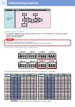
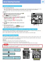
To change all the indoor unit addresses using an arbitrary wired remote controller.
(The method is available when the addresses have already been set automatically.)
(When communication wirings of 2 or more refrigerant lines are interconnected for central control)
NOTE
You can change the addresses of indoor units in each refrigerant line using an arbitrary wired remote controller.
∗
Enter the address check/change mode and change the addresses.
2
4
1
3
8
5, 7
6
ON / OFF
SET
TEST
FILTER
RESET
CL
SAVE
SWING/FIX
VENT
UNIT LOUVER
CODE No
.
UNIT
R.C.
No.
No.
MODE
FAN
SET DATA
SETTING
ON / OFF
SET
TEST
FILTER
RESET
CL
SAVE
SWING/FIX
VENT
UNIT LOUVER
CODE No
.
UNIT
R.C.
R C
No.
No.
MODE
FAN
SET DATA
SETTING
Cancels the line selection
Push to finish setting.
Finish
If no number appears on UNIT No., no outdoor unit exists on the line.
Push
CL
button and select another line following step
2
.
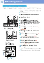
(Execute it while the units are stopped.)
1
Push and hold the TIME
and
TEST
buttons at the same time for more than 4 seconds.
At first, the line 1 and CODE No.
AC
(Address Change) are indicated on the LCD display.
2
Push
UNIT LOUVER
(left side of the button) and
SWING/FIX
buttons repeatedly to select a system address.
3
Push the
SET
button.
• The address of one of the indoor units connected to the selected refrigerant line is indicated on the LCD
display and the fan and louvers of the unit are activated.
At first, the current indoor unit address is displayed in SET DATA. (No system address is indicated.)
4
Push the TIME
/
buttons repeatedly to change
the value of the indoor unit address in SET DATA.
Change the value in SET DATA to that of a new address.
5
Push the
SET
button to confirm the new address on SET
DATA.
6
Push the
UNIT LOUVER
button (left side of the button) repeatedly
to select another address to change.
Each time you push the button, the indoor unit numbers
in a refrigerant line are indicated one after another.
Only the fan and louvers of the selected indoor unit are
activated.
Repeat steps
4
to
6
to change the indoor unit addresses
so as to make each of them unique.
7
Push the
SET
button.
(All the segments on the LCD display light up.)
8
Push the
TEST
button to finish the procedure.
Monitoring Function of Remote Controller Switch (con-
tinue)
Содержание MMY-MAP0804 Series
Страница 1: ...Quick reference R410A FILE NO A11 005 ...
Страница 49: ...MEMO ...
Страница 50: ...MEMO ...
Страница 51: ...MEMO ...
Страница 52: ......

