


17
1600XPi Series UPS Installation and Operation Manual – 60616-014
9 Operating Modes
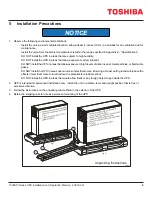
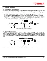
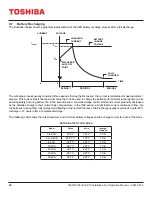
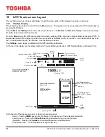
9.1 Static-Bypass (Stop operation)
If the UPS unit is severely overloaded or develops an internal fault, power flow is automatically switched from the unit’s main
circuit to the bypass circuit. Power flow through the bypass is shown in the following illustration. This change-over occurs
automatically in phase in less than one-quarter cycle of the input waveform. The switching period is not long enough to
cause interruptions to occur in most loads.
•
If the power flow is transferred to the bypass circuit due to an internal fault the UPS will continue to supply power to
the load through the bypass and indicate a system fault message (see
“24.3 System Fault Messages” on page 52).
•
If the power flow is transferred to the bypass circuit due to an overload condition (see “24.4 System Warning Messages”
), then the power flow will automatically transfer from the UPS’s bypass circuit back to the inverter circuit
after removing the overload if set to do so (AutoXfer parameter (Cmd ID 660)).
POWER FLOW IN BYPASS FOR ALL MODELS
Output
Power
Line Filter
Inverter
*Static Switch
Isolation
Transformer
Input
Power
Input
Fuse
Power Flow
Bypass
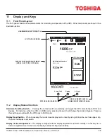
* Switches are
solid state
devices.
MCCB
Output
Fuse
Surge
Absorber*
Batteries
+
–
Rectifier/
Chopper
Negative Bus
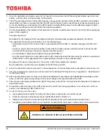
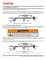
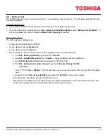
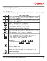
9.2 On-Line (Run operation)
The following illustration shows circuit power flow when the UPS is operating normally in the On-Line mode. The UPS
rectifier, including a boost chopper circuit, converts AC input power to DC power. The boost chopper circuit maintains a
constant voltage, with current limiting, for charging the batteries. The inverter section generates a high quality sinu soidal
output voltage. The unit’s batteries are always maintained in a constantly charged state when the UPS is in the run operation
mode.
Output
Power
Line Filter
Inverter
*Static Switch
Isolation
Transformer
Input
Power
Input
Fuse
Power Flow
Bypass
* Switches are
solid state
devices.
MCCB
Output
Fuse
Surge
Absorber*
Batteries
+
–
Rectifier/
Chopper
POWER FLOW IN ON-LINE MODE FOR ALL MODELS
Negative Bus
*Surge Absorber is connected as indicated in 3.6–10kVA units. Surge Absorber is connected at the point between the Line Filter and Input Fuse in 14–22kVA units.
Содержание 1600XPi SERIES
Страница 2: ......
Страница 6: ...This Page Left Intentionally Blank ...
Страница 10: ...This Page Left Intentionally Blank ...
Страница 78: ...This Page Left Intentionally Blank ...
Страница 88: ...This Page Left Intentionally Blank ...
Страница 118: ...This Page Left Intentionally Blank ...
Страница 120: ...C2 1600XPi Series UPS Installation and Operation Manual 60616 014 5 2 6 kVA Dimensions ...
Страница 121: ...C3 1600XPi Series UPS Installation and Operation Manual 60616 014 8 10 kVA Dimensions ...
Страница 122: ...C4 1600XPi Series UPS Installation and Operation Manual 60616 014 14 22 kVA Dimensions ...
Страница 130: ......
Страница 132: ...E2 1600XPi Series UPS Installation and Operation Manual 60616 014 FIGURE E 2 8 22KVA BATTERY CABINET OUTLINE ...
Страница 138: ...This Page Left Intentionally Blank ...
Страница 139: ......


