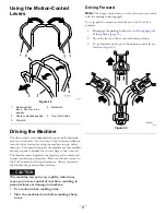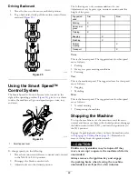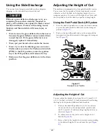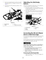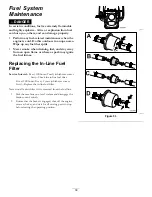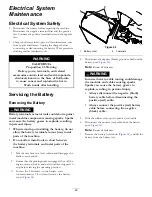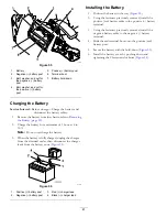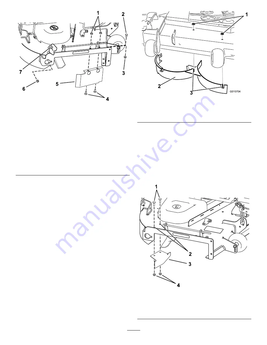
g190737
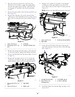
Figure 35
1.
Locknuts—front of
discharge plate (install
after baffle is removed)
5.
Baffle guard—54-inch
decks
2.
Hex-head bolt—forward
hole in deck (install after
baffle is removed)
6.
Locknut (5/16 inch)
3.
Locknut—forward hole in
deck (install after baffle is
removed)
7.
Carriage bolt (5/16 x 3/4
inch)
4.
Carriage bolts—front of
discharge plate (install
after baffle is removed)
9.
Locate the baffle guard at the front edge of the side
discharge opening (
).
10.
Remove the fasteners securing the baffle guard and the
right baffle to the mower deck (
).
Note:
Remove the baffle guard and retain all fasteners.
11.
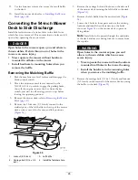
Remove the 2 locknuts (5/16 inch) securing the welded
posts of the right baffle to the top of the mower deck
at center and right of center positions (
G010704
1
2
3
g010704
Figure 36
1.
Locknut (5/16 inch)
3.
Welded posts (right baffle)
2.
Right baffle
12.
Remove the carriage bolt and locknut securing the right
baffle to the top of the mower deck and remove the
right baffle from the mower deck (
13.
Install the fasteners removed previously at the front
holes in the discharge plate and forward hole in the
deck (
).
14.
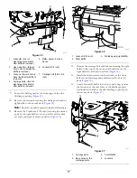
Locate the cutoff baffle in the loose parts bag, remove
the fasteners at the rear holes of the discharge plate,
and install the baffle at the side-discharge opening on
the mower deck (
).
g190735
Figure 37
1.
Carriage bolts
3.
Cutoff baffle
2.
Rear holes in the
discharge plate
4.
Locknuts
27
Содержание TimeCutter HD X5450
Страница 55: ...Schematics g203461 Electrical Diagram Rev A 55 ...
Страница 56: ...Notes ...
Страница 57: ...Notes ...
Страница 58: ...Notes ...

