for normal cutting. For TRANSPORT, move the control
to MOW, push the control to the right, then up to FAST
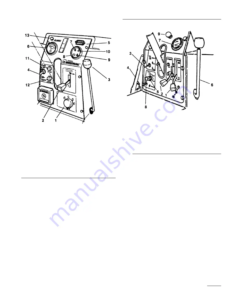
Cutting Unit Lift Lever (Figures 12 & 13)—The lift
lever has three positions: LOWER, RAISE, and NEU-
TRAL. To lower the cutting units to the ground, move
the lift lever forward.
When lowering the cutting units, make sure the
hydraulic cylinder is completely retracted before releas-
ing the lift lever. The cutting units won’t operate unless
the cylinder is retracted.
To raise the cutting units, pull the lift lever rearward to
the RAISE position.
Cutting Unit Drive Switch (Figures 12 & 13) —The
switch has two positions: ENGAGE and DISENGAGE.
The toggle switch engages the electromagnetic clutch to
drive the cutting units. An amber light on the dash indi-
cates when the reels are turning. Pull the switch lever
out to move from disengage to engage.
Hour Meter (Figures 12 & 13)—Indicates the total
hours of machine operation. The hour meter starts
whenever the key switch is turned to “ON.”
Fuse Holders (Fig. 12 & 13)— To replace a fuse, turn
the knob counter-clockwise and remove the fuse from
the case. Install the fuse, insert the knob and turn it
clockwise to secure it in the panel.
Diesel Models: Temperature Gauge (Fig. 12)—
Registers coolant temperature in the system.
Diesel Models:
Oil
Pressure Light (Fig. 12)—Glows if
the engine oil pressure drops below a safe level.
Diesel Models: Water Temperature Light (Figure
12)—This light glows and the engine automatically
15
Controls
Figure 12 (Diesel Models)
1. Ignition switch & cover
2. Throttle
3. Cutting unit lift lever
4. Cutting unit drive switch
S. Hour meter
6. Water temperature gauge
7. Oil pressure light
8. Amp gauge
9. Glow plug indicator
10. High water temperature shut-down light
11. Engine
fuse
12. Accessory
fuse
13. Reel operating light
Figure 13 (Gasoline Models)
1. Throttle control
2. Choke control
3. Cutting unit drive switch
4. Parking brake
5. Ignition switch
6. Cutting unit left lever
7. Hour meter
8. Fuse holder
9. Hood
latch
10. High water temperature shut-down light
Содержание reelmaster 216
Страница 24: ...Figure 28 Figure 29 Figure 30 Figure 31 24 Maintenance ...
Страница 34: ......
Страница 35: ......
Страница 36: ......


