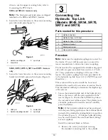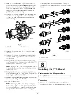
9. Slide the PTO shaft tubes together until they are
fully collapsed. Verify that the
inside
tube does not
protrude into the cross and bearing section of the
outer tube (Figure 16). If this happens,
more
will
have to be cut off the inside tube, to correct the
problem. Proceed to next step.
10. Measure the distance the inside tube protrudes into
the cross and bearing section of the outer tube
(Figure 16). Add this distance to the dimension
attained in step 8.
Figure 16
1.
Cut off
2.
Inside tube
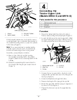
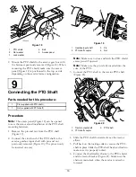
11. Separate the two halves of the PTO shaft (Figure 17,
illustration 1).
12. Measure the distance from the end of each tube to
its safety shield (Figure 17, illustration 1). Record
the distances.
13. Using the dimensions determined in step 8, locate,
mark and cut off the shield and tube from each PTO
half (Figure 17, illustrations 2 & 3).
Note:
More will have to be cut off the inside tube if
it was protruding into the cross and bearing section
of the outer tube.
14. Using the dimensions determined in step 11, locate,
mark and cut off just the safety shields to expose the
tubes Figure 17, illustrations 4 & 5.
15. Carefully deburr the ends of the tubes with a file and
remove all the filings from the tubes.
16. Grease the inside tube.
Note:
Telescoping tubes must always overlap by
1/2 of their length in normal operation and at least
1/3 of their length in all working conditions. During
transport, when the drive line is not rotating, the
telescoping tubes must have a suitable overlap to
maintain the tubes alignment and allow them to slide
freely.
Figure 17
1.
Measure here
8
Installing the PTO Shield
Parts needed for this procedure:
1
PTO Shield
Procedure
1. Remove the 4 bolts, lock washers and flat washers
secured to the rear of the aerator gear box (Figure 18).
15


