background image

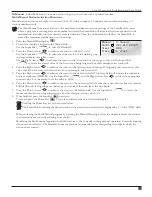
Clock Set:

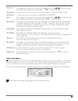
This setting sets the current time. Use the Left and Right Arrow Keys 

 to select the Hours 

and Minutes parameters then use the Input Dial 

 to modify the values.

Clock Mode:

Use this menu item to select the clock mode between Am/Pm (12-Hour) and 24-Hour mode.

Date Mode:

Use this menu item to select the date mode: MMDDYY or DDMMYY.

Date:

This setting sets the current date. Use the Left and Right Arrow Keys 

 to select the Month, 

Date and Year parameters then use the Input Dial 

 to modify the values.

Day Change:

This setting sets the “day change” time. The “day change” is the specified time that the SmartHub 

will advance the date. The default day change is 12:00 am. Adjusting the day change time will allow 

programs to start throughout the night on the same active day schedule. Programs with runtimes 

beyond the day change time are allowed to finish.

CSG Address:

This setting sets the CSG (Central SmartHub Group) address. Lynx uses this address to identify 

different SmartHub groups. 

SAT Address:

This setting sets the SmartHub address. Each SmartHub must be given a unique  

SmartHub address. Lynx uses this address to identify individual SmartHubs when sending SmartHub 

specific commands.

Sta Delay:

This setting sets the station delay, in seconds, before any individual station activates.  

This feature helps avoid water hammer.

Max Sim Sta:

This setting sets the maximum number of  simultaneously operating stations. This threshold will 

be applied to all programs and manual irrigation functions. Each program can be set with a lower 

limitation if  necessary. This setting is set in Lynx and downloaded to the SmartHub. 

Set Password:

Use this command to set a password to prevent unauthorized access to the menu system.  

The menu system can still be reviewed but no values changed.

Display Adj:

This setting adjusts the contrast of the LCD screen. Use the Input Dial 

 to darken or 

lighten the text display.

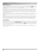
% (Percent) Adjust

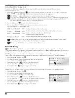
 The percent adjust function allows you to fine tune irrigation programs, stations, or the satellite as a whole (as in, all 

Programs and all stations connected to the satellite). With weather conditions changing constantly, Percent Adjust allows 

you to tune runtimes in your system easily without changing all the runtime values individually in the program.

Use the arrow keys and Input Dial to modify percentage values for the Satellite, selected program, or selected station.

 Percent Adjust does not affect manual operations or scheduled list activity.

Percent Adjust...

Satellite:   100%

Program:    P01 

100%

Station:   S001 

100%

29

Lynx® SmartHub Installation and User Guide

Содержание Lynx SmartHub

Страница 1: ...Lynx SmartHub for LSM GAC Installation and User Guide DEC and DAC Series...

Страница 2: ...unication Cable 18 Communicating with the SmartHub 19 Layout 1 Local 19 Layout 2 Wired Lynx 20 Layout 3 Wireless 20 Radio Communication FIU to SmartHub 21 Changing the Frequency of the Radio 22 Operat...

Страница 3: ...onduit of various diameters to enable power field ground and communication wiring to be routed into the pedestal for connection A mounting bolt positioner and basic mounting hardware components are in...

Страница 4: ...n from direct sunlight rain wind and snow as possible IMPORTANT Do not mount the controller where it is exposed to direct spray from the irrigation system Steps 1 Drill two pilot holes 6 15 25cm apart...

Страница 5: ...3 Strip the power cables and secure them to the terminal block Figure 3 Reference Table 1 for the appropriate type of power connection 4 Reinstall the power supply cover 5 Apply power to the controll...

Страница 6: ...r 6 Pour concrete into the formed foundation hole Press the mounting bolt positioner into the concrete until it is flush and level with the foundation surface and aligned with the conduit 7 Finish the...

Страница 7: ...lush with or below ground level and should be protected from damage using a valve box A 2 Measure the ground resistance per the instructions provided with the ground test instrument If reading is 10 o...

Страница 8: ...x SmartHub Installation and User Guide 8 2 4m 8 2 4m 8 2 4m 8 2 4m 8 2 4m No solenoid power or communication cables within this zone pedestal or gateway concrete pad grounding rod grounding plate Figu...

Страница 9: ...block Reference Table 1 and Figure 7 for the appropriate type of power connection 3 Reinstall the power supply cover 4 Apply power to the controller WARNING AC POWER WIRING MUST BE INSTALLED AND CONNE...

Страница 10: ...without conduit All field wiring splices must be accessible to facilitate troubleshooting and or service Steps 1 Route communication cable from the controller to the station module installation locat...

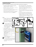
Страница 11: ...oubleshooting install wires with the same color code as the station wires Each station can activate up to two DC Latching Solenoids Out to additional modules Station Wires The Lynx SmartHub output boa...

Страница 12: ...oute communication cable from the controller to the station decoder module installation location The maximum wire length between the controller and the decoder module is 6 800 2072 m 2 Secure the comm...

Страница 13: ...on 3 s solenoid wires Station 4 Orange Wire Connect to one of Station 4 s solenoid wires Red Power Communication Wire Black Power Communication Wire Output Circuit 1 AC Solenoid Black Black Each stati...

Страница 14: ...ng listed in Table 2 below Table 2 Power Cable Circuit Rating Minimum KVA Recommended Minimum Spacing 0 3 6 inches 15 cm 3 10 12 inches 30 cm 10 20 24 inches 60 cm 20 50 36 inches 90 cm 50 100 48 inch...

Страница 15: ...d wire to the ground rod or plate s wire If the ground rod or plate is not pre wired use a 10 AWG bare copper wire 5 Drive a 5 8 by 8 17mm x 2 5m copper clad steel rod into well moistened soil not les...

Страница 16: ...Max B C 500 150m Max D 1000 300m Max Figure 10 For upgrades of existing systems we recommend adding one ground point Detail A at the end of each main communication line valve box black white DEC SG LI...

Страница 17: ...to the controller 2 Connect the cable wires to the Pressure Sensor Terminals labeled C in Figure 11 Red wire to the terminal black wire to the terminal 3 Place the controller s switch to ON Master Val...

Страница 18: ...of splicing device Using an appropriate splicing kit such as Scotchcast 82 A1 or equivalent is recommended Placing the cable splice in a small valve box for protection and accessibility is a good inst...

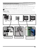
Страница 19: ...nd cabinet Smart Hubs are interchangeable with each other Layout 1 Local The SmartHub is attached to the Field Interface Unit by a Wireline The SmartHub typically resides in the office with the Lynx c...

Страница 20: ...1 2 3 4 MENU POWER AUTO LYNX SmartHub 1 SmartHub 2 Wired Lynx 1 2 3 The Wireline connection is limited to about 9 miles Layout 3 Wireless The Lynx SmartHub DEC RS 1000 DR digital radio and modem comm...

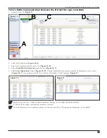
Страница 21: ...ton Figure 15 C 5 Click Start Operations button Figure 15 D Certain SmartHub information should be displayed on the screen Figure 16 If communication fails the software will display a fail message Fig...

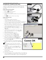
Страница 22: ...eboot computer 3 Plug USB cable into a USB port and Serial port on radio Figure 18 4 Connect Phoenix power cable into 12V power supply Plug other end into DC IN port on radio Figure 19 5 Plug in 12V p...

Страница 23: ...nation selection is handled through the Personal Communications Industry Association PCIA 800 759 0300 and an application must be submitted to the FCC There is a PCIA fee and FCC license fee that must...

Страница 24: ...rams or other settings that impact watering Off Mode When placed in Off mode the SmartHub will not execute any watering operation whether it is program or manually initiated Any watering operation wil...

Страница 25: ...diagnostic information See page 33 10 Station Settings button allows you to modify station parameters Within this setting you can disable the station from any activity hold station watering for a spec...

Страница 26: ...will save any setting modifications and return the user to the Home display Home display examples The GW line displays the address of the controller In the example above the address of the SmartHub is...

Страница 27: ...ion page 31 Press the Stop button to cancel Pause Button The Pause button can be used to pause any running irrigation program or all irrigation activity Stop Button Use the Stop function to cancel all...

Страница 28: ...s This command resets all station settings by selecting Yes After selecting Yes press the Up or Down Arrows to activate There is a short countdown before the command executes during which the command...

Страница 29: ...nds Sta Delay This setting sets the station delay in seconds before any individual station activates This feature helps avoid water hammer Max Sim Sta This setting sets the maximum number of simultane...

Страница 30: ...he station to edit in this field Choose from Station 01 through the SmartHub maximum station count of 500 LSM or 250 GAC Allows the operator to set the percent adjust for the selected station if desir...

Страница 31: ...ne when plants trees or lawn need extra water A new sod lawn for example would benefit from a grow in program for a couple of weeks or month 5 For interval schedules it is necessary to define today s...

Страница 32: ...ub to implement changes SBF Lists are disabled when the controller is in Local Mode Manual Watering The Manual Watering functions are used for additional watering if the irrigation program is not suff...

Страница 33: ...rst value For our example select station 12 5 Press the Right Arrow to advance the cursor to the next entry field This entry field will indicate the runtime in hours and minutes HH MM Use the Input Di...

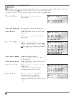
Страница 34: ...display the date and time of the last power down PD and last power up PU Press the Down arrow to scroll down the informations Menu PowerUp Detect DC 2 500 DB 1 1 0 0 PD 01 11 19 14 22 20 PU 01 12 19 0...

Страница 35: ...command allows the user to run diagnostic tests that send messages to decoders and modules The faceplate will show the last test performed at the TM The tests include communication pictured solenoid...

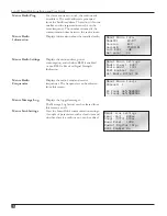
Страница 36: ...ot RSSI is Received Signal Strength Indication Menu Radio Settings Radio Power 040 Radio Addr 1181 RSSI Enable No Set Radio Dflts No Menu Radio Frequencies Displays the radio s send and receive freque...

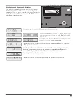
Страница 37: ...they are on D1L1 0 24A D1L2 0 24A D2L1 0 24A D2L2 0 24A The display will also show the load currents by individual wires of a two wire communication line 1 open 0 2 open 0 The display will show the Ra...

Страница 38: ...ffected daughterboard s alarm LED blinks on and off Phase Current Imbalance Alarm D1L1 High Amp D2 A 0 500 D1L1 A 0 750 D2 A 0 500 Triggered when load current of one wire is 2x higher than the opposit...

Страница 39: ...butor or outside the United States call 951 688 9221 Neither Toro nor Toro Warranty Company is liable for indirect incidental or consequential damages in connection with the use of equipment including...

Страница 40: ...ion www toro com 1 877 345 8676 Form Number 373 0965 Rev C WARNING Cancer and Reproductive harm www P65Warnings ca gov For more information please visit www toro com CAProp65 Patent www ttcopats com 4...

Отзывы: