


g032677
Figure 4
1.
O-rings
4.
Align the bearing and the flocked seal that you
removed in step
in the slots in the left bracket,
and rotate them to the original position (
g032562
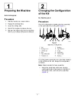
Figure 5
Left Drive Configuration
1.
Left bracket
7.
Bearing cover
2.
Bearing
8.
Locknut
3.
Flocked seal
9.
O-ring
4.
Assembled parts
10.
Flocked seal
5.
Hex-socket screw
11.
Bearing
6.
Right bracket
12.
Shaft collar
5.
Align the assembled shaft collar, bearing, and
flocked seals in the slots in the right bracket, and
rotate the parts to the original position (
).
6.
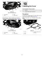
Prepare the idler assembly as follows:
A.
Remove the hex-socket screw securing the
bushing and the spring to the idler assembly
(
g032676
Figure 6
Left Drive Configuration
B.
Remove the spring, flip it over, and install it
as shown in
.
C.
Secure the spring and the bushing with the
screw that you removed in step
4
Содержание 04650
Страница 14: ...Notes...
Страница 16: ......