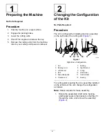
Toro 04650 Скачать руководство пользователя страница 10

9

Installing the Pulleys and
the Belt

Parts needed for this procedure:

1

Belt

1

Drive pulley

1

Driven pulley

2

Washer (as required)

Procedure

1.

Use the hex-socket screw (5/16 x 1/2 inch) to

secure the drive pulley to the groomer shaft
(

Figure 19

).

g032464

Figure 19

1.

Drive pulley

4.

Driven pulley

2.

Hex-socket screw (5/16 x
1/2 inch)

5.

Washers

3.

Locknut (3/8 inch)—torque
it to 20 to 26 N∙m (15 to 19
ft-lb)

2.

Use the locknut (3/8 inch) to secure the driven
pulley to the brush shaft (

Figure 19

).

Note:

Use a wrench on the flats of the brush

shaft to keep the shaft from spinning (

Figure 20

).

Torque the locknut to 20 to 26 N∙m (15 to 19
ft-lb).

g033566

Figure 20

1.

Flats

3.

Check the alignment of the pulleys (

Figure 21

).

g032675

Figure 21

4.

If the pulleys are not aligned, change the position
of the driven pulley by removing the washer or
adding the other washer as necessary.

5.

Install the belt as follows:

A.

Position the belt over the drive pulley
(

Figure 22

).

B.

Use a 1/2-inch wrench or a 3/16-inch hex
key to release the spring tension on the
idler.

C.

Position the other end of the belt over the
driven pulley (

Figure 22

) and allow the idler

to return to the original position.
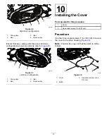
10


Содержание 04650

Страница 1: ...he adapter kit sold separately Drive housing assembly 1 Bracket assembly drive side 1 4 Hex socket screw 1 4 x 3 4 inch 2 Install the drive housing to the bearing bracket Flange nut 5 16 inch 2 Flange...

Страница 2: ...g the drive assembly on the right side of the cutting unit Figure 1 g032561 Figure 1 Right Drive Configuration 1 Nut 7 Bearing 2 Bearing cover 8 Right bracket 3 Left bracket 9 O ring 4 Bolt 10 Shaft c...

Страница 3: ...2 Rotate the bearing and the flocked seal in the right bracket so that they fit through the slots and remove them Figure 3 g032557 Figure 3 3 Check to ensure that the O ring in each bracket stays in...

Страница 4: ...socket screw 11 Bearing 6 Right bracket 12 Shaft collar 5 Align the assembled shaft collar bearing and flocked seals in the slots in the right bracket and rotate the parts to the original position Fi...

Страница 5: ...he left side of the cutting unit it has left hand threads g032589 Figure 8 1 Bearing screw 5 Secure the driveshaft to the driveshaft adapter Figure 9 and torque it to 149 to 162 N m 110 to 120 ft lb N...

Страница 6: ...12 Proceed with the installation as described in the other procedures 4 Installing the Drive Housing to the Bearing Bracket Parts needed for this procedure 1 Drive housing assembly 1 Bracket assembly...

Страница 7: ...lange head bolts 5 16 x 1 inch 2 flange nuts 5 16 inch and a retaining ring as shown in Figure 14 Note This step applies to units both with or without a groomer g032460 Figure 14 1 Flange nut 5 16 inc...

Страница 8: ...non drive side as shown in Figure 16 g032462 Figure 16 1 Bracket assembly non drive side 3 Install the small retaining ring and a flocked seal onto the splined end of the brush shaft Figure 17 g03246...

Страница 9: ...e cutting unit as shown in Figure 18 g032509 Figure 18 1 Flange head bolt 5 16 x 1 inch 2 Flange nut 5 16 inch 8 Positioning the Brush No Parts Required Procedure 1 Loosen the 2 nuts and bolts securin...

Страница 10: ...19 Note Use a wrench on the flats of the brush shaft to keep the shaft from spinning Figure 20 Torque the locknut to 20 to 26 N m 15 to 19 ft lb g033566 Figure 20 1 Flats 3 Check the alignment of the...

Страница 11: ...re 23 Left Drive Configuration 1 Drive pulley 3 Idler 2 Belt 4 Driven pulley 10 Installing the Cover Parts needed for this procedure 1 Cover 3 Hex socket screw 1 4 x 3 8 inch Procedure Use the 3 hex s...

Страница 12: ...de of the reel support plate Figure 25 Note Insert the pry bar between the top of the reel shaft and the backs of the reel blades so that the reel does not move Important Do not contact the cutting ed...

Страница 13: ...not move Important Do not contact the cutting edge of any blades with the pry bar this may damage the cutting edge or cause a high blade Important The insert on the left side of the cutting unit has...

Страница 14: ...Notes...

Страница 15: ...technical documentation has been compiled as required per Part B of Annex VII of 2006 42 EC We will undertake to transmit in response to requests by national authorities relevant information on this...

Страница 16: ......

Отзывы: