


Declaration of Incorporation
The Toro Company, 8111 Lyndale Ave. South, Bloomington, MN, USA declares that the following unit(s)
conform(s) to the directives listed, when installed in accordance with the accompanying instructions onto certain
Toro models as indicated on the relevant Declarations of Conformity.
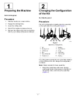
Model No.
Serial No.
Product Description
Invoice Description
General Description
Directive
04650
—
Rear Roller Brush,
Greensmaster 3250-D,
TriFlex 3300, and 3400
Series DPA Cutting Units
with Universal Groomer
REAR ROLLER BRUSH,
NEW GEN DPA GREENS CU
Rear Roller Brush
2006/42/EC
Relevant technical documentation has been compiled as required per Part B of Annex VII of 2006/42/EC.
We will undertake to transmit, in response to requests by national authorities, relevant information on this partly
completed machinery. The method of transmission shall be electronic transmittal.
This machinery shall not be put into service until incorporated into approved Toro models as indicated on the
associated Declaration of Conformity and in accordance with all instructions, whereby it can be declared in
conformity with all relevant Directives.
Certified:
Authorized Representative:
Marcel Dutrieux
Manager European Product Integrity
Toro Europe NV
Nijverheidsstraat 5
2260 Oevel
Belgium
John Heckel
Sr. Engineering Manager
8111 Lyndale Ave. South
Bloomington, MN 55420, USA
February 1, 2019
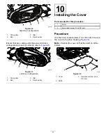
Содержание 04650
Страница 14: ...Notes...
Страница 16: ......