background image

The Toro Warranty

Two-Year or 1,500 Hours Limited Warranty

Conditions and Products Covered

The Toro Company and its affiliate, Toro Warranty Company, pursuant
to an agreement between them, jointly warrant your Toro Commercial
product (“Product”) to be free from defects in materials or workmanship
for 2 years or 1,500 operational hours*, whichever occurs first. This
warranty is applicable to all products with the exception of Aerators
(refer to separate warranty statements for these products). Where a
warrantable condition exists, we will repair the Product at no cost to you
including diagnostics, labor, parts, and transportation. This warranty
begins on the date the Product is delivered to the original retail purchaser.
* Product equipped with an hour meter.

Instructions for Obtaining Warranty Service

You are responsible for notifying the Commercial Products Distributor or
Authorized Commercial Products Dealer from whom you purchased the
Product as soon as you believe a warrantable condition exists. If you need
help locating a Commercial Products Distributor or Authorized Dealer, or
if you have questions regarding your warranty rights or responsibilities,
you may contact us at:

Toro Commercial Products Service Department
Toro Warranty Company
8111 Lyndale Avenue South
Bloomington, MN 55420-1196

952–888–8801 or 800–952–2740
E-mail: [email protected]

Owner Responsibilities

As the product owner, you are responsible for required maintenance and
adjustments stated in your

Operator's Manual

. Repairs for product issues

caused by failure to perform required maintenance and adjustments are not
covered under this warranty.

Items and Conditions Not Covered

Not all product failures or malfunctions that occur during the warranty
period are defects in materials or workmanship. This warranty does not
cover the following:

Product failures which result from the use of non-Toro replacement
parts, or from installation and use of add-on, or modified non-Toro
branded accessories and products.

Product failures which result from failure to perform recommended
maintenance and/or adjustments.

Product failures which result from operating the Product in an abusive,
negligent, or reckless manner.

Parts consumed through use that are not defective. Examples of parts
which are consumed, or used up, during normal Product operation
include, but are not limited to, brake pads and linings, clutch linings,
blades, reels, rollers and bearings (sealed or greasable), bed knives,
spark plugs, castor wheels and bearings, tires, filters, belts, and certain
sprayer components such as diaphragms, nozzles, and check valves.

Failures caused by outside influence, including, but not limited to,
weather, storage practices, contamination, use of unapproved fuels,
coolants, lubricants, additives, fertilizers, water, or chemicals.

Failure or performance issues due to the use of fuels (e.g. gasoline,
diesel, or biodiesel) that do not conform to their respective industry
standards.

Normal noise, vibration, wear and tear, and deterioration. Normal
“wear and tear” includes, but is not limited to, damage to seats due to
wear or abrasion, worn painted surfaces, scratched decals or windows.

Parts

Parts scheduled for replacement as required maintenance are warranted
for the period of time up to the scheduled replacement time for that part.
Parts replaced under this warranty are covered for the duration of the
original product warranty and become the property of Toro. Toro will make
the final decision whether to repair any existing part or assembly or replace
it. Toro may use remanufactured parts for warranty repairs.

Deep Cycle and Lithium-Ion Battery Warranty

Deep cycle and Lithium-Ion batteries have a specified total number
of kilowatt-hours they can deliver during their lifetime. Operating,
recharging, and maintenance techniques can extend or reduce total
battery life. As the batteries in this product are consumed, the amount
of useful work between charging intervals will slowly decrease until the
battery is completely worn out. Replacement of worn out batteries,
due to normal consumption, is the responsibility of the product owner.
Note: (Lithium-Ion battery only): Pro-rated after 2 years. Refer to the
battery warranty for additional information.

Lifetime Crankshaft Warranty (ProStripe 02657 Model

Only)

The Prostripe which is fitted with a genuine Toro Friction Disc and
Crank-Safe Blade Brake Clutch (integrated Blade Brake Clutch (BBC) +
Friction Disc assembly) as original equipment and used by the original
purchaser in accordance with recommended operating and maintenance
procedures, are covered by a Lifetime Warranty against engine crankshaft
bending. Machines fitted with friction washers, Blade Brake Clutch (BBC)
units and other such devices are not covered by the Lifetime Crankshaft
Warranty.

Maintenance is at Owner’s Expense

Engine tune-up, lubrication, cleaning and polishing, replacement of filters,
coolant, and completing recommended maintenance are some of the
normal services Toro products require that are at the owner’s expense.

General Conditions

Repair by an Authorized Toro Distributor or Dealer is your sole remedy
under this warranty.

Neither The Toro Company nor Toro Warranty Company is liable for
indirect, incidental or consequential damages in connection with the
use of the Toro Products covered by this warranty, including any
cost or expense of providing substitute equipment or service during
reasonable periods of malfunction or non-use pending completion
of repairs under this warranty. Except for the Emissions warranty
referenced below, if applicable, there is no other express warranty. All
implied warranties of merchantability and fitness for use are limited to
the duration of this express warranty.

Some states do not allow exclusions of incidental or consequential
damages, or limitations on how long an implied warranty lasts, so the above
exclusions and limitations may not apply to you. This warranty gives you
specific legal rights, and you may also have other rights which vary from
state to state.

Note Regarding Emissions Warranty

The Emissions Control System on your Product may be covered by
a separate warranty meeting requirements established by the U.S.
Environmental Protection Agency (EPA) and/or the California Air Resources
Board (CARB). The hour limitations set forth above do not apply to the
Emissions Control System Warranty. Refer to the Engine Emission Control
Warranty Statement supplied with your product or contained in the engine
manufacturer’s documentation.

Countries Other than the United States or Canada

Customers who have purchased Toro products exported from the United States or Canada should contact their Toro Distributor (Dealer) to obtain
guarantee policies for your country, province, or state. If for any reason you are dissatisfied with your Distributor's service or have difficulty obtaining
guarantee information, contact your Authorized Toro Service Center.

374-0253 Rev F


Содержание 03188

Страница 1: ...ter 3100 D or 3105 D Traction Unit Model No 03188 Serial No 407900000 and Up Model No 03189 Serial No 407900000 and Up Model No 03190 Serial No 407900000 and Up Model No 03191 Serial No 407900000 and Up Model No 03192 Serial No 400000000 and Up Register at www Toro com Original Instructions EN 3443 362 ...

Страница 2: ...rized Service Dealer or Toro Customer Service and have the model and serial numbers of your product ready Figure 1 identifies the location of the model and serial numbers on the product Write the numbers in the space provided Important With your mobile device you can scan the QR code on the serial number plate if equipped to access warranty parts and other product information g280515 Figure 1 1 Lo...

Страница 3: ...ons to avoid serious personal injury Read and understand the contents of this Operator s Manual before starting the machine Use your full attention while operating the machine Do not engage in any activity that causes distractions otherwise injury or property damage may occur Do not put your hands or feet near moving components of the machine Do not operate the machine without all guards and other...

Страница 4: ...d blade can break and a piece of the blade could be thrown toward you or bystanders resulting in serious personal injury or death Inspect the blade periodically for wear or damage Use care when checking the blades Wrap the blades or wear gloves and use caution when servicing the blades Only replace or sharpen the blades never straighten or weld them On multi bladed machines take care as rotating 1...

Страница 5: ...included postcard for information on obtaining the Parts Catalog Review the material and save it in an appropriate place Note Determine the left and right sides of the machine from the normal operating position 1 Installing the Reel Grease Fitting Parts needed for this procedure 1 Straight grease fitting Procedure Install the grease fitting on the reel motor side of the cutting unit Refer to Figur...

Страница 6: ...O ring 2 Cap screws may come assembled Procedure Important Before installing the reel motors obtain and install the counter weights or other accessories on the opposite side of the cutting units from the reel motors as described in the instructions provided with the weights or accessories 1 Install the cutting units onto the traction unit refer to the traction unit Operator s Manuals for instructi...

Страница 7: ...lb Attachments Accessories A selection of Toro approved attachments and accessories is available for use with the machine to enhance and expand its capabilities Contact your Authorized Service Dealer or authorized Toro distributor or go to www Toro com for a list of all approved attachments and accessories To ensure optimum performance and continued safety certification of the machine use only gen...

Страница 8: ...oper bedknife to reel contact Perform this procedure even when the quality of cut is acceptable 1 Slowly rotate the reel in a reverse direction listening for reel to bedknife contact Note The adjustment knobs have detents corresponding to 0 022 mm 0 0009 inch bedknife movement for each indexed position Refer to Adjusting the Bedknife to the Reel page 9 2 Test the cutting performance by inserting a...

Страница 9: ... low You will need the following tools to complete this procedure Shim 0 05 mm 0 002 inch Part No 125 5611 Cutting performance paper Part No 125 5610 1 Position the cutting unit on a flat level work surface 2 Turn the bedbar adjusting screws counterclockwise to ensure that the bedbar does not contact the reel Figure 9 g003322 Figure 9 1 Bedbar adjusting screw 3 Tip the cutting unit to expose the b...

Страница 10: ...009 inch Do not overtighten the adjusting screws 12 Test the cutting performance refer to Checking the Cutting Unit page 8 Adjusting the Rear Roller 1 Adjust the rear roller brackets Figure 11 to the desired height of cut range by positioning the required amount of spacers below the side plate mounting flange Figure 11 per the HOC Chart g003324 Figure 11 1 Spacer 3 Side plate mounting flange 2 Rol...

Страница 11: ... shop roller brackets before the cutting unit is lowered to the shop floor or removed from the traction unit Figure 13 g341821 Figure 13 1 Clevis pin always installed in the top square hole in the side plate 3 Shop roller assembly in lowered shop position 2 Side plate Raise the shop roller brackets after the cutting unit is raised to the operating position Figure 14 g341820 Figure 14 1 Clevis pin ...

Страница 12: ...e between the bottom of the screw head and the face of the bar is the height of cut g011864 Figure 16 1 Gauge bar 3 Nut 2 Height adjusting screw 3 Hook the screw head on the cutting edge of the bedknife and rest the rear end of the bar on the rear roller Figure 17 4 Rotate the adjusting screw until the front roller contacts the gauge bar Figure 17 Adjust both ends of roller until the entire roller...

Страница 13: ...0 375 inch More 2 35 mm 1 375 inches More 6 Less 0 Less 5 Normal 1 Normal 6 13 mm 0 500 inch More 2 38 mm 1 500 inches More 7 Less 1 Less 6 Normal 2 Normal 7 16 mm 0 625 inch More 3 41 mm 1 625 inches More 8 Less 2 Less 6 Normal 3 Normal 7 19 mm 0 750 inch More 4 44 mm 1 750 inches More 8 Less 2 Less 7 Normal 3 Normal 8 22 mm 0 875 inch More 4 48 mm 1 875 inches More 9 Less 3 Less 7 Normal 4 Norma...

Страница 14: ...ch adjustment spacers 3 Side plate pad 2 1 4 inch adjustment spacers 4 Lower fixed spacers do not adjust Height of Cut Chart Model 03192 HOC Setting No of 1 4 inch Rear Spacers No of Thin Rear Spacers 32 mm 1 25 inches 5 0 34 mm 1 33 inches 5 1 35 mm 1 38 inches 5 2 38 mm 1 50 inches 6 0 40 mm 1 58 inches 6 1 42 mm 1 65 inches 6 2 45 mm 1 75 inches 7 0 46 mm 1 83 inches 7 1 48 mm 1 90 inches 7 2 5...

Страница 15: ... to 0 500 inch 112 8910 27 inch 6 9 mm 9 5 to 50 8 mm EdgeMax 112 8956 32 inch 0 270 inch 0 375 to 2 00 inches 114 9388 Model 03188 89 90 27 inch 6 9 mm 9 5 to 50 8 mm Standard 114 9389 Model 03191 32 inch 0 270 inch 0 375 to 2 00 inches 114 9390 Model 03192 27 inch 9 3 mm 12 7 to 50 8 mm Heavy Duty 114 9391 32 inch 0 370 inch 0 500 to 2 00 inches Warm season grasses may require the Low HOC bedkni...

Страница 16: ...f Evaluator effective HOC range 0 75 to 6 00 inches 19 to 152 mm Aggressiveness of Cut The aggressiveness of cut has a significant impact on the performance of the cutting unit Aggressiveness of cut refers to the angle of the bedknife relative to the ground Figure 22 The best cutting unit setup depends on your turf conditions and desired results Experience with the cutting unit on your turf will d...

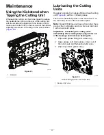
Страница 17: ... unit Figure 24 with No 2 lithium grease There are 2 lubrication points on the front roller 2 on the rear roller and 1 at the reel motor spline Note Model 03192 does not have a front roller there are only the 2 lubrication points on the rear roller and 1 at the reel motor spline Important Lubricating the cutting units immediately after washing helps purge water out of the bearings and increases be...

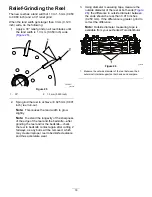
Страница 18: ...the reel and the bedknife after grinding the reel and or the bedknife check the reel to bedknife contact again after cutting 2 fairways as any burrs will be removed which may create improper reel to bedknife clearance and thus accelerate wear 3 Using diameter measuring tape measure the outside diameter of the reel at both ends Figure 26 the difference in outside diameter between the ends should be...

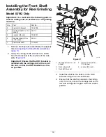
Страница 19: ...mblies page 11 2 Using the carriage bolts and locknuts install front HoC brackets to the top hole of the side plate Figure 27 Important Ensure that the HOC bracket is installed with the carriage bolt at the top of the slot so that the HOC bracket is as low as possible g361153 Figure 27 1 Carriage bolt 3 8 x 1 1 2 inches 4 Hex head bolt 5 16 x 1 1 8 inches 2 Front roller shaft 5 Locknut 3 8 inch 3 ...

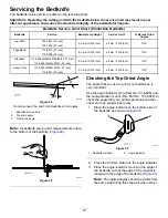
Страница 20: ...h 10 5 g027268 Figure 28 Recommended Top and Front Bedknife Grind Angles 1 Bedknife service limit 2 Top grind angle 3 Front grind angle Note All bedknife service limit measurements relate to the bottom of the bedknife Figure 29 g007165 Figure 29 Checking the Top Grind Angle The angle that you use to grind your bedknives is very important Use the angle indicator Toro Part No 131 6828 and the angle ...

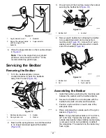
Страница 21: ...t Figure 33 g003334 Figure 33 1 Bedbar bolt 2 Locknut 4 Remove each bedbar bolt allowing the bedbar to be pulled downward and removed from machine bolt Figure 33 Account for 2 nylon washers and 1 stamped steel washer on each end of the bedbar Figure 34 g003335 Figure 34 1 Bedbar bolt 3 Steel washer 2 Nut 4 Nylon washer Assembling the Bedbar 1 Install the bedbar positioning the mounting ears betwee...

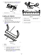
Страница 22: ...screw threads 3 Apply anti seize compound to the screws and install the bedknife to the bedbar as follows Figure 36 g279161 Figure 36 1 Bedbar 3 Screw 2 Bedknife A Torque the 2 outer screws to 1 N m 10 in lb refer to Figure 37 B Working form the center of the bedknife torque the screws to 23 to 28 N m 200 to 250 in lb refer to Figure 37 g279162 Figure 37 1 Bedknife screw tool 3 Torque to 23 to 28 ...

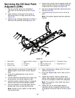
Страница 23: ...ing tension nut 3 Flange bushing 6 Locknut 9 Hardened washer 7 Apply anti seize compound to the threads of the bedbar adjuster screw that fit into the adjuster shaft 8 Thread the bedbar adjuster screw into the adjuster shaft 9 Loosely install the hardened washer spring and spring tension nut onto the adjuster screw 10 Install the bedbar positioning the mounting ears between the washer and the bedb...

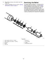
Страница 24: ...d Kit includes all the bearings bearing nuts inner seals and outer seals to rebuild a roller The Roller Rebuild Tool Kit includes all the tools and the installation instructions required to rebuild a roller with the roller rebuild kit Refer to your parts catalog or contact your authorized Toro distributor for assistance g007790 Figure 39 1 Roller Rebuild Kit Part No 114 5430 6 Bearing nut 2 Roller...

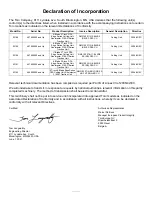
Страница 25: ...00 and Up 8 Blade 32 inch DPA Edge Series Cutting Unit Reelmaster 3100 D Series Traction Unit RM3100 32IN 8 BLADE ES RR DPA CU Cutting Unit 2006 42 EC 03192 400000000 and Up 27 inch 8 Blade EdgeSeries DPA Cutting Unit Reelmaster 3105 D Traction Unit RM3105 27IN 8BLD RR ES NO FRT ROLLER CU Cutting Unit 2006 42 EC Relevant technical documentation has been compiled as required per Part B of Annex VII...

Страница 26: ...tion of the original product warranty and become the property of Toro Toro will make the final decision whether to repair any existing part or assembly or replace it Toro may use remanufactured parts for warranty repairs Deep Cycle and Lithium Ion Battery Warranty Deep cycle and Lithium Ion batteries have a specified total number of kilowatt hours they can deliver during their lifetime Operating r...

Отзывы: