Donaldson Company, Inc. © 1995
41
5.3
∆∆∆∆∆
P Control Calibration
The only user calibration is the zero adjustment
of the display. Due to either slight changes in
electronic components over time or pressure
differentials within the plant environment,
occasionally the display may show something
other than 0.0 while at rest. Use the following
procedure to recalibrate the zero point.
1. Power the
∆
P Control for a minimum of
30 minutes to stabilize the operating
temperature.
2. Remove power from the
∆
P Control so that
the display shuts down.
3.
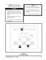
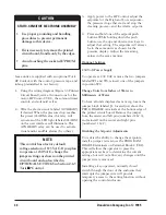
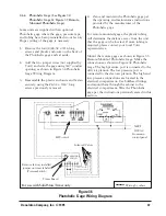
Press and hold
the LOW SET, HIGH SET,
and ALARM SET keys while reapplying
power to the
∆
P Control. Continue to hold
these keys while the
∆
P Control goes
through a power-up routine. This is
indicated by sequentially displaying "8" in
each digit, and then displaying "0.0" (see
Figure 32
∆
P Control Display).
4. Release all three keys. The new calibration
automatically stores in memory.
5.4
Outlet Damper Adjustment
Blower adjustments can be made by testing the
duct system flow rate and adjusting the volume
control damper to the desired system flow rate.
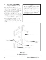
The airflow through the Downsized Downflo
collector may be adjusted by using the outlet
damper located on the top of the unit (see
Figure 1 SDF-4 Phantom View). Turn the two
knobs to loosen them. While still grasping the
knobs, slide the damper plate. The more the
damper is closed, the more the airflow will be
restricted. The damper will give the maximum
airflow through the collector when fully open.
5.5
Operating Checks
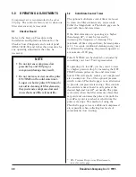
Monitor the exhaust visually. Exhaust should
remain visually clean. If a leak develops, it will
be first noticed as a visual puff of dust
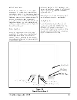
immediately after a cleaning pulse. A red light
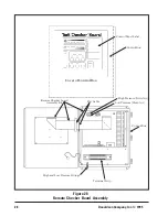
on the Checker board will also indicate that
there may be a problem.
Monitor filter element pressure drop by means
of the visual display on the Checker board. See
the Installation and Operations Manual for the
Checker board diagnostic and control panel.
Equilibrium pressure drop (stabilized
∆
P) is
generally 3-4 inches water gage for seasoned
filters, but 1-6 inches water gage is considered
normal.
NOTE
Compare the blower motor amperage
draw to the motor manufacturer's
nameplate amperage rating. Operating
amperage greater than the manufacturer's
recommendation will cause damage.
NOTE
At initial start-up or with any new filter
elements, the blower may overload
because of airflow higher than design
level. If this happens, partially close the
volume control damper and check blower
motor amperage draw.

