34
Donaldson Company, Inc. © 1995
Some units are supplied with an optional Torit
∆
P Control, with the control, pressure taps, and
tubing preinstalled in our factory.
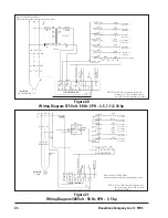
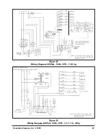
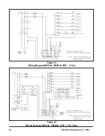
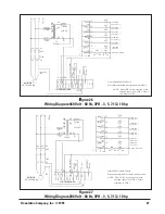
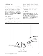
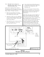
1. Using the wiring diagram (Figure 33 Printed
Circuit Board), wire all connections for the
motor,
∆
P Control (TB1), the solenoid timer
control, and solenoid valves.
2. Wire the alarm circuit labeled AUXILIARY,
if desired. When the pressure drop reaches
the preset ALARM value, the relay will
actuate and the LED light labeled ALARM
on the user interface will illuminate. The
AUXILIARY relay can be used to actuate
visual and/or audible alarms (by others).
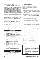
CAUTION
STATIC-SENSITIVE ELECTRONIC ASSEMBLY
• Use proper grounding and handling
procedures to prevent permanent
damage to this device.
• If it is necessary to remove the printed
circuit board, handle only by the edges.
• Avoid touching the socketed E
2
PROM
pins.
NOTE
This control has a factory default
voltage selection of 115 VAC. If you plan
to operate at 230 VAC, change the
jumper settings as shown on the printed
circuit board and as described in
OPTIONAL SETTINGS in Section 2.6.5
Torit
∆∆∆∆∆
P Control.
3. Apply power to the
∆
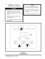
P Control, adjust the
setpoints for the High and Low setpoints—
the pressure drops that start and stop the
cleaning process—and the Alarm setpoint.
4. Press and hold one of the setpoint push
buttons. While holding down the push
button, use the up and down arrow keys to
adjust that setting. The setpoints will always
be in the same units as chosen for the
pressure display. Adjust the remaining
values in the same manner.
Optional Settings
230 Volt Power Supply
To operate at 230 VAC remove the two jumpers
labeled W1 and W3, reinsert one of the jumpers
in position W2.
Change Units from Inches of Water to
Millimeters of Water
To have all units displayed as mm wg, locate the
jumper block labeled J1, located just above the
PROG DISABLE terminals at the bottom edge of
the printed circuit board. Remove the jumper
from the center and left pins (numbered 2 & 3),
and reinstall on the center and right pins
(numbered 1 & 2).
Disabling the Setpoint Adjustments
To restrict the ability to change the setpoints,
install a jumper wire across the PROGRAM
DISABLE terminals on Terminal Block 2 (TB2).
This will allow the operator to press the
appropriate set keys to determine the current
settings, but will not allow any changes until the
jumper wire is removed.
Installing a key-operated, normally closed
switch through the door of the enclosure that
interrupts the jumper wire will provide
temporary access to the setting function without
opening the control enclosure.

