20
Donaldson Company, Inc. © 1995
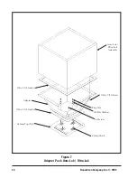
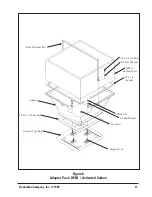
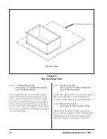
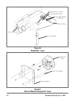
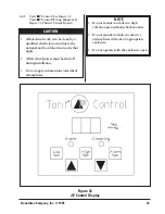
2.5.13 Explosion Vent Pack
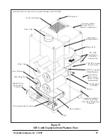
(See Figure 14 Explosion Vent Pack)
Remove the cover plate bolts and the cover plate
from the side of the SDF cabinet. Using the same
cover plate bolts, attach the 12 x 12 explosion
vents to the side of the SDF cabinet. Be sure to
apply silicone sealant between the bolted flanges
and the cabinet, as shown in Figure 14 Explosion
Vent Pack. Tighten the bolts only until the vent
frame flange starts to bend. Do not overtighten.
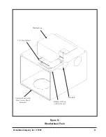
The 12 x 12 weather cover should be used for
outside applications. Apply silicone sealant only
along the bolted flange of the weather cover.
Attach the weather cover to the explosion vent
flange using bolts, lock washers and nuts as
shown. Also bend the 1.4 inch wide tab 180
degrees over and press firmly against the
explosion vent frame. Do this on both sides of
the weather cover.
For operating precautions, technical data and
rearming instructions for the explosion vents, see
the Torit Explosion Vent Manual
IOM-72087-01.
2.6 Electrical Installation
The Downsized Downflo dust collector is
available with four versions of electrical
components:
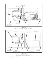
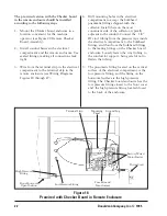
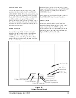
1. Pre-wired with the Checker board on the
unit (see Figure 16 Pre-Wired with Checker
Board on Unit)
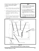
2. Unwired with the Checker board on the
unit (see Figure 17 Unwired with Checker
Board on Unit)
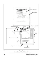
3. Pre-wired with the Checker board in a
remote enclosure (see Figure 18 Pre-Wired
with Checker Board in Remote Enclosure)
4. Unwired with the Checker board in a
remote enclosure (see Figure 19 Unwired
with Checker Board in Remote Enclosure).
The pre-wired version with the Checker board
on the unit has been completely wired at the
factory. Before it is ready for operation, a plug
must be attached to the power cord and the unit
must be connected to a duct.
The unwired version with the Checker board on
the unit has only the solenoid valves and the
temperature sensor wired at the factory.
A proper-sized motor starter needs to be
mounted externally or in the electrical
compartment. A proper-sized power cord and
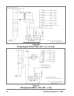
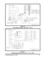
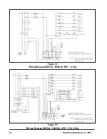
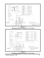
plug also needs to be installed. Using the wiring
diagrams (Figures 20 through 27) make the
proper connections to the blower motor, blower
motor starter, and the Checker board.
All electrical apparatus should be properly sized
for the required voltage and motor full load
amperage.
NOTE
• All electrical work must be done by a
qualified electrician according to local
codes.
• The plug attached to the power cord
must be for the correct voltage as
designated.
CAUTION
• Explosion relief vents are required on
some applications.
• Consult with an insurance underwriter
or a NFPA Manual to determine proper
vent sizing requirements.
• Vents installed on dust collection
equipment within a building must relieve
to the outside of the building to
minimize chances of a secondary
explosion.
• Consult the proper authority to
determine proper method of venting the
dust collection equipment.
• Torit equipment does NOT contain
explosion relief vents, except on special
order.
CAUTION
Remote controls are required for units
handling combustible or explosive dusts.

