Donaldson Company, Inc. © 1995
29
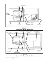
With the blower motor starter turned on, check
operation of the solenoid valves. When the
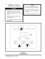
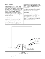
Checker board is used, press and hold the
CONSTANT CLEAN push button and pulsing
will begin. The valves should open and close
continuously with a factory set interval time of
10 seconds between each cleaning pulse.
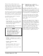
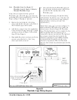
Figure 29
SDF Solid-State Timer Wiring Diagram
POWER
SUPPLY
TIMING
LOGIC
CONTROL
LOGIC
CONTROL BOX
ON TIME
OFF TIME
PRESSURE
SWITCH
PROGRAM PINS
PROGRAM LUG
SOLENOID VALVES
4FU
3AMP
L1 L2
SOL
COM 1
3
4
2
5
6
X1
115V
X2
H2
460V
ITGS
H3
H1
IM
IM
STOP
START
X1
115V
X2
H3
H2
H1
H4
H4
230V
FAN
I MTR
IOL
IT3
IT2
IT1
IM
IL3
IL2
IL1
3FU
2FU
1FU
L1
L2
L3
230V 30
60N
If the model SDF is purchased with a solid state
timer in the unit instead of the Checker board,
the timer will be wired to the solenoid valves.
If the timer is to be remote mounted, it will be
furnished unwired. A properly sized motor
starter needs to be mounted in addition to the
timer. Using the wiring diagram in Figure 29
SDF Solid-State Timer Wiring Diagram, make
the proper connections to the blower motor,
blower motor starter, and solid state timer.
After attaching the plug and starting the blower
motor, check for proper rotation. It should be
clockwise when looking down at the top of the
blower motor. Also, reference the rotation
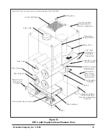
sticker on the blower housing (see Figure 1
SDF-4 Phantom View). Proper blower rotation is
extremely important. If the blower is running in
the wrong direction, it will only deliver
approximately 40% of its rated air volume.
Interchange any two power wire leads (3 phase
only) on the plug to reverse rotation.
CAUTION
Do not interchange a power lead and
the ground wire.
Disconnect electrical power before
servicing any electrical component.
CAUTION


