38
Donaldson Company, Inc. © 1995
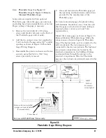
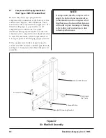
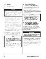
Figure 37
Air Manifold Assembly
Solenoid Coil
Solenoid Valve
Diaphragm
Air Valve
Manifold Weldment
Manifold Mounting Bracket
2.7
Compressed Air Supply Installation
(See Figure 1 SDF-4 Phantom View)
Remove the plastic pipe plug from the
compressed air connection at the bottom of the
collector (see Figure 1 SDF-4 Phantom View)
and connect the compressed air supply line. Use
thread-sealing tape or pipe sealant on all
compressed air connections. Use quick-
disconnect fittings if possible. Be sure that all
compressed air components are adequately sized
to meet the maximum system requirements of
1.1 scf per pulse at 90-100 psig supply pressure.
If the compressed air inlet adapter is used to
convert the NPT threads to British pipe threads,
see Figure 3 Compressed Air Inlet Adapters for
assembly.
NOTE
It is important that the compressed air
supply be both oil and moisture free.
Contamination in the compressed air
line that is used to clean filter elements
will result in poor cleaning or cleaning
valve failure and a reduction in dust
collector performance.

