26
Base Plate
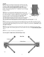
Step 21
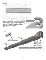
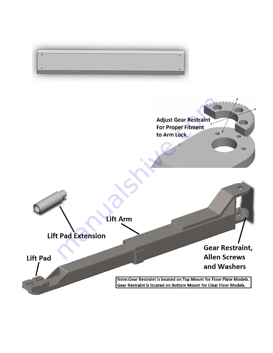
: Install base plate with 4 - M8 x 15mm Countersink Screws. (Fig 17)
Arms
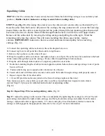
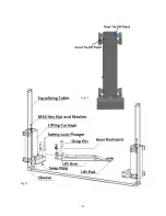
STEP 22:
The “half moon” gear restraints on each lifting
arm are already installed. Loosen Allen Screws Gear
restraints will need to be adjusted once installed on lifting
carriages. Position the lifting arms on the carriages using the
included securing arm pins . Check for proper engagement
of the arm restraints – arm lock and safety gear restraints
should fully engage the gear on the arm. After checking that
the safety gear restraints and arm lock engage properly,
tighten Allen bolts on gear restraints.
(Fig 18, 19)
Fig 17
Fig 18
Fig 19
Содержание QJY240C
Страница 9: ...9...
Страница 23: ...23 Fig 12 Fig 12...
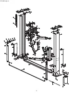
Страница 32: ...34 Parts Diagram...
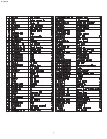
Страница 33: ...35 Parts List...
Страница 34: ...36 COMPANY INFO BACK PAGE...

