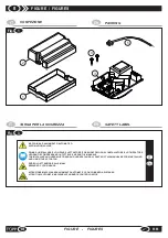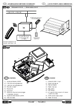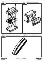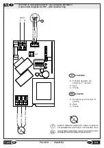
You can request the following accessories;
% No.1 rain sensor;
% No.1 remote/radio control TR8.
&
Do not use any parts and accessories that are not
"original" as this could endanger the safety and efficiency of
the power unit and invalidate the warranty.
&
Spare parts and accessories must be requested
exclusively from your local distributor or the manufacturer,
communicating the type, model, serial number and year of
construction of the power unit.
IT
APPENDIX
7
7.1
MAINTENANCE
7.2
DEMOLITION
7.3
ACCESSORIES AND SPARE PARTS
If the power unit does not function properly, contact
the manufacturer. Any repairs on the power unit must
be made exclusively by the manufacturer's qualified
experts. TOPP does not accept any liability for repairs
made by unauthorized persons.
The power unit and its accessories are used with elements
that do not require routine or special maintenance as a
general rule. Under particularly extreme conditions (very dirty
premises, frequent use, abrupt temperature changes, etc.) or
in case of outdoor installation (limited to the sensors) it is
necessary to check at least once every six months, the seal of
the fastening systems and gaskets, the state of the wires and
connections. With the same frequency, check that the control
unit and its accessories (rain and wind sensor) do not show
signs of damage or overheating. In particular, for
precautionary reasons, we recommend replacing them as
soon as they show signs of wear due to exposure to sunlight
or extreme weather (dullness of coloring and/or deformity of
the external casings, discoloration, opaque spots, cracks
Demolition of the power unit must be handled in respect of the
legislation in force on the subject of environmental
safeguards. It is therefore necessary to separate the parts of
the power unit depending on the type of material.
17
EN
RR
key 2) of the radio control device enabled during
programming, make sure dip-switch no. 2 is
ON
and proceed
as follows:
% press the smooth key (key) on the radio control device to
send the open signal to the actuator;
% press the knurled key (key 2) to send the stop signal to
the actuator;
% press the knurled key (key 2) to send the closure signal;
% press the smooth key (key 1) to send the stop signal.
To drive the actuator in “deadman” mode with the first pair of
keys (key 1 and key 2) of the radio control device enabled
during programming, turn dip-switch no. 2
OFF
and proceed
as follows:
% press the smooth key (key 1) to send the the open signal
to the actuator;
In radio mode the minimum range is about 10-20 meters
depending on the shape of the room in which the RR unit is
located and charged status of the batteries.
6.8
RANGE OF THE RADIOCONTROL DEVICE
and/or porosity on the sensitive surface of the rain sensor).
% release the smooth key (key 1) to send the stop signal;
% hold the knurled key (key 2) pressed to send the closure
signal to the actuator;
% release the knurled key (key 2) to send the stop signal.
&
The deadman mode is not recommended if the motors
are driven by remote/radio control as it runs the batteries
down very quickly.
INSTALLATION AND USE INSTRUCTIONS
Содержание RR
Страница 23: ......

