Tab.1
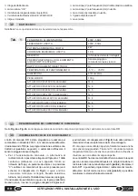
lists the technical data that characterize the device.
SUPPLY VOLTAGE
OUTPUT VOLTAGE
POWER ABSORBED AT NO LOAD
SERVICE
POSSIBLE CONNECTION TO EXTERNAL
DEVICES
DOUBLE ELECTRICAL INSULATION
WORKING TEMPERATURE
DIMENSIONS
GROSS WEIGHT
C20 230V ACTUATORS CONNECTABLE
230V - 50Hz
230V - 50Hz
2W
Depending on motors connected
Rain sensor or
manual control via cable
Yes
-5°C ÷ +50°C
87x53x32mm
100 g
N. 6
Tab.
1
MAX OUTPUT CURRENT
1,3 A
C30 230V ACTUATORS CONNECTABLE
N. 4
C40 230V ACTUATORS CONNECTABLE
N. 5
ACK4 230V ACTUATORS CONNECTABLE
N. 4
T50 230V ACTUATORS CONNECTABLE
N. 4
T80 230V ACTUATORS CONNECTABLE
N. 3
SL60 230V ACTUATORS CONNECTABLE
N. 4
C240 230V ACTUATORS CONNECTABLE
N. 3
3.2
TECHNICAL DATA
The RR mini control unit has been designed and produced to
drive a 230V ~ actuator in manual mode using the TR8 radio
control device (programming and use of this device are
described in section 6.4 and below) or in automatic mode via
the rain sensor connected to it.
@
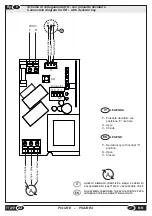
For manual operation, alternative to radio control, it is
possible to connect the J1 input of the control unit to a
deviator key with central “0” position (see connection
diagram in
Fig.9
), equipped with “deadman” switch
(using the special cable supplied on request by Topp),
which will control the actuator. This solution, however,
does not permit installation of the rain sensor.
Automatic function follows a predefined logic. When it rains,
3.3
LIST OF PARTS AND DIMENSIONS
3.4
TECHNICAL OPERATING INFORMATION
the rain sensor connected to the J1 input (see connection
diagram in
Fig.8
) automatically sends the closure order to the
motor connected to the control unit. The forced manual re-
opening is allowed also with enabled rain sensor.After 10
minutes (approx.) from the opening command, if the sensor is
still active, the windows close; while if it isn’t active,they
remain open.
The RR mini has several operating modes, which can be set
by programming the dip-switches (
par.6.2
). Using key SP1 it
is possible to program the radio control device while, using
the red and green led (
par.6.3
), it is possible to monitor the
status of the control unit.
13
EN
RR
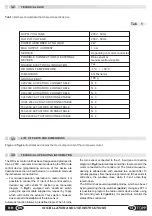
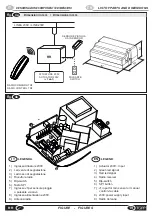
Fig. 4
and
fig.4a
illustrates and names the main components of the unit power control.
INSTALLATION AND USE INSTRUCTIONS
Содержание RR
Страница 23: ......


