background image

IT

1 - DECLARATION OF CONFORMITY . . . . . . . . . . . . . . . . . . . . . . . . . . . . . . . . . . . . . . . . . . . . . . . . . pag 02

2 - GENERAL REMARKS . . . . . . . . . . . . . . . . . . . . . . . . . . . . . . . . . . . . . . . . . . . . . . . . . . . . . . . . . . . pag 12
    2.1

 - General instructions . . . . . . . . . . . . . . . . . . . . . . . . . . . . . . . . . . . . . . . . . . . . . . . . . . . . . . . . . . pag 12

    2.2

 - Installer . . . . . . . . . . . . . . . . . . . . . . . . . . . . . . . . . . . . . . . . . . . . . . . . . . . . . . . . . . . . . . . . . . . . pag 12

    2.3

 - User . . . . . . . . . . . . . . . . . . . . . . . . . . . . . . . . . . . . . . . . . . . . . . . . . . . . . . . . . . . . . . . . . . . . . . pag 12 

    2.4 

- Field of application  . . . . . . . . . . . . . . . . . . . . . . . . . . . . . . . . . . . . . . . . . . . . . . . . . . . . . . . . . . . pag 12

    2.5 

- Warranty . . . . . . . . . . . . . . . . . . . . . . . . . . . . . . . . . . . . . . . . . . . . . . . . . . . . . . . . . . . . . . . . . . . pag 12

    2.6 

- Technical assistance . . . . . . . . . . . . . . . . . . . . . . . . . . . . . . . . . . . . . . . . . . . . . . . . . . . . . . . . . . pag 12

    2.7 

- Packing. . . . . . . . . . . . . . . . . . . . . . . . . . . . . . . . . . . . . . . . . . . . . . . . . . . . . . . . . . . . . . . . . . . . pag 12

3 - TECHNICAL DESCRIPTION . . . . . . . . . . . . . . . . . . . . . . . . . . . . . . . . . . . . . . . . . . . . . . . . . . . . . . pag 12
    3.1

 - Rating plate and "CE" marking  . . . . . . . . . . . . . . . . . . . . . . . . . . . . . . . . . . . . . . . . . . . . . . . . . . pag 12

    3.2

 - Technical data  . . . . . . . . . . . . . . . . . . . . . . . . . . . . . . . . . . . . . . . . . . . . . . . . . . . . . . . . . . . . . .  pag 13


3.3 

- List of parts and dimensions . . . . . . . . . . . . . . . . . . . . . . . . . . . . . . . . . . . . . . . . . . . . . . . . . . . . pag 13

    3.4

 - Technical information about operation . . . . . . . . . . . . . . . . . . . . . . . . . . . . . . . . . . . . . . . . . . . . . pag 13

4 - SAFETY FEATURES . . . . . . . . . . . . . . . . . . . . . . . . . . . . . . . . . . . . . . . . . . . . . . . . . . . . . . . . . . . . pag 14
    4.1

 - General instructions . . . . . . . . . . . . . . . . . . . . . . . . . . . . . . . . . . . . . . . . . . . . . . . . . . . . . . . . . . pag 14


4.2

 - Safety devices. . . . . . . . . . . . . . . . . . . . . . . . . . . . . . . . . . . . . . . . . . . . . . . . . . . . . . . . . . . . . . . pag 14


4.3

 - Safety plates . . . . . . . . . . . . . . . . . . . . . . . . . . . . . . . . . . . . . . . . . . . . . . . . . . . . . . . . . . . . . . . . pag 14

    4.4

 - Residual hazards . . . . . . . . . . . . . . . . . . . . . . . . . . . . . . . . . . . . . . . . . . . . . . . . . . . . . . . . . . . . pag 14

5 - INSTALLATION. . . . . . . . . . . . . . . . . . . . . . . . . . . . . . . . . . . . . . . . . . . . . . . . . . . . . . . . . . . . . . . . . pag 14
    5.1

 - General instructions . . . . . . . . . . . . . . . . . . . . . . . . . . . . . . . . . . . . . . . . . . . . . . . . . . . . . . . . . . pag 14


 5.2 

- Installation of the sensors . . . . . . . . . . . . . . . . . . . . . . . . . . . . . . . . . . . . . . . . . . . . . . . . . . . . . . pag 14


5.3

 - Installation of the RR . . . . . . . . . . . . . . . . . . . . . . . . . . . . . . . . . . . . . . . . . . . . . . . . . . . . . . . . . . pag 14

    5.4

 - Electrical connections . . . . . . . . . . . . . . . . . . . . . . . . . . . . . . . . . . . . . . . . . . . . . . . . . . . . . . . . . pag 15

6 - USE AND OPERATION. . . . . . . . . . . . . . . . . . . . . . . . . . . . . . . . . . . . . . . . . . . . . . . . . . . . . . . . . . . pag 15
    6.1

 - General instructions . . . . . . . . . . . . . . . . . . . . . . . . . . . . . . . . . . . . . . . . . . . . . . . . . . . . . . . . . . pag 15

    6.2

 - Led . . . . . . . . . . . . . . . . . . . . . . . . . . . . . . . . . . . . . . . . . . . . . . . . . . . . . . . . . . . . . . . . . . . . . . .  pag 15


6.3 

- Programming dip-switches . . . . . . . . . . . . . . . . . . . . . . . . . . . . . . . . . . . . . . . . . . . . . . . . . . . . . pag 15


6.4 

- Radio control TR8 . . . . . . . . . . . . . . . . . . . . . . . . . . . . . . . . . . . . . . . . . . . . . . . . . . . . . . . . . . . . pag 16


 6.5 

- Resetting of the RR . . . . . . . . . . . . . . . . . . . . . . . . . . . . . . . . . . . . . . . . . . . . . . . . . . . . . . . . . . . pag 16


6.6 

- Programming the radio control . . . . . . . . . . . . . . . . . . . . . . . . . . . . . . . . . . . . . . . . . . . . . . . . . . pag 16


6.7 

- Use of the remote/radio control . . . . . . . . . . . . . . . . . . . . . . . . . . . . . . . . . . . . . . . . . . . . . . . . . . pag 16


6.8 

- Remote/radio control range. . . . . . . . . . . . . . . . . . . . . . . . . . . . . . . . . . . . . . . . . . . . . . . . . . . . . pag 16

7 - USE AND OPERATION. . . . . . . . . . . . . . . . . . . . . . . . . . . . . . . . . . . . . . . . . . . . . . . . . . . . . . . . . . . pag 17


7.1 

- Maintenance . . . . . . . . . . . . . . . . . . . . . . . . . . . . . . . . . . . . . . . . . . . . . . . . . . . . . . . . . . . . . . . . pag 17

    7.2

 - Demolition. . . . . . . . . . . . . . . . . . . . . . . . . . . . . . . . . . . . . . . . . . . . . . . . . . . . . . . . . . . . . . . . . . pag 17

    7.3 

- Accessories and spare parts . . . . . . . . . . . . . . . . . . . . . . . . . . . . . . . . . . . . . . . . . . . . . . . . . . . . pag 17

8 - FIGURES . . . . . . . . . . . . . . . . . . . . . . . . . . . . . . . . . . . . . . . . . . . . . . . . . . . . . . . . . . . . . . . . . . . . . . pag 18

GUARANTEE CERTIFICATE . . . . . . . . . . . . . . . . . . . . . . . . . . . . . . . . . . . . . . . . . . . . . . . . . . . . . . . . pag 23

INDEX

EN

11

EN

RR

INSTALLATION AND USE INSTRUCTIONS

Содержание RR

Страница 1: ...ISTRUZIONI PER L INSTALLAZIONE E L USO COD 8P5014 IT UNITÀ DI ALIMENTAZIONE E COMANDO MOTORI 230V POWER UNIT AND 230V MOTOR DRIVER RR VER 0 0 REV 11 17 INSTALLATION AND USE INSTRUCTIONS EN ...

Страница 2: ... Radio Equipment Directive RED 2014 53 EU Direttiva Rohs II 2011 65 UE Attuazione Italiana DLgs 4 marzo 2014 n 27 Rohs II Directive 2011 65 EU e inoltre dichiara che sono state applicate le seguenti norme armonizzate and also declares that the following harmonised standards have been applied EN 50581 2012 EN 300 220 2 V3 1 1 e i seguenti documenti tecnici and the following technical documents EN 6...

Страница 3: ...otezione pag 06 4 3 Targhe relative alla sicurezza pag 06 4 4 Rischi residui pag 06 5 INSTALLAZIONE pag 06 5 1 Avvertenze generali pag 06 5 2 Installazione del sensore pioggia pag 07 5 3 Installazione della centrale pag 07 5 4 Collegamento elettrico pag 07 6 USO E FUNZIONAMENTO pag 07 6 1 Avvertenze generali pag 07 6 2 Programmazione dei dip switch pag 08 6 3 Led pag 08 6 4 Radiocomando TR8 pag 08...

Страница 4: ...anuale Il presente manuale è parte integrante dell unità di alimentazione e deve obbligatoriamente essere conservato dall installatore assieme a tutta la documentazione allegata per futuri riferimenti Il presente manuale è destinato al proprietario agli utilizzatori agli installatori e ai tecnici abilitati alla manutenzione ed ha lo scopo lo scopo di fornire tutte le informazioni necessarie affinc...

Страница 5: ...ante deviatore con posizione 0 centrale con comando di tipo uomo presente ved schema di collegamento di Fig 9 il quale andrà a comandare l attuatore collegato Questa soluzione tuttavia non permette l installazione del sensore pioggia Il funzionamento automatico segue una logica predefinita Quando piove il sensore pioggia collegato all ingresso J1 vedi schema di collegamento di Fig 8 invia alla cen...

Страница 6: ...tallazione degli attuatori sui serramenti l azionamento automatico degli stessi può accidentalmente generare il seguente rischio residuo Rischio residuo Pericolo di schiacciamento o trascinamento di parti del corpo inserite tra la parte mobile e la parte fissa del serramento Frequenza di esposizione Accidentale e quando l installatore o l utilizzatore decida di compiere un azione volontaria scorre...

Страница 7: ...llazione che rilascia al cliente la dichiarazione di conformità del collegamento e o dell impianto realizzato Prima di eseguire il collegamento elettrico degli attuatori all unità di alimentazione assicurarsi di aver tolto l alimentazione dalla linea La linea di alimentazione elettrica a cui viene collegata l unità di alimentazione deve essere conforme ai requisiti previsti dalla legislazione vige...

Страница 8: ...iusura automatico da sensore pioggia e lo converte in comando di chiusura il led verde rimane acceso con luce fissa mentre il led rosso lampeggia fino a quando il sensore non rimane attivo 6 4 RADIOCOMANDO TR8 Il radiocomando TR8 Fig 7 comanda in modalità manuale il motore collegato alla RR mediante trasmissione radio Per abilitare all uso il radiocomando è necessario che il ricevitore della centr...

Страница 9: ...ia possibile vedere i movimenti dell attuatore durante la programmazione procedere nel seguente modo premere e mantenere premuto il tasto SP1 fino a quando il led rosso non si accende con luce fissa dopo circa 5 secondi premere e mantenere premuto il tasto liscio della coppia di tasti del radiocomando che si vuole abilitare F Dopo qualche secondo il led rosso esegue 4 lampeggi e poi si spegne rila...

Страница 10: ...ossono compromettere la sicurezza e l efficienza 7 3 ACCESSORI E RICAMBI A RICHIESTA 10 ISTRUZIONI PER L INSTALLAZIONE E L USO IT RR dell unità di alimentazione I ricambi e gli accessori devono essere richiesti esclusivamente al rivenditore di fiducia o al fabbricante comunicando il tipo il modello il numero di serie e l anno di costruzione dell unità ...

Страница 11: ...afety plates pag 14 4 4 Residual hazards pag 14 5 INSTALLATION pag 14 5 1 General instructions pag 14 5 2 Installation of the sensors pag 14 5 3 Installation of the RR pag 14 5 4 Electrical connections pag 15 6 USE AND OPERATION pag 15 6 1 General instructions pag 15 6 2 Led pag 15 6 3 Programming dip switches pag 15 6 4 Radio control TR8 pag 16 6 5 Resetting of the RR pag 16 6 6 Programming the r...

Страница 12: ...ve in respect of the safety conditions foreseen in the country of use Do not install the power unit outside the premises subject to atmospheric agents Do not use the power unit in premises with a potentially explosive atmosphere 2 2 INSTALLER 2 3 THE USER 2 4 FIELD OF APPLICATION 2 5 WARRANTY 2 6 TECHNICAL ASSISTANCE 2 7 PACKING Before installing the device the installer must read and understand a...

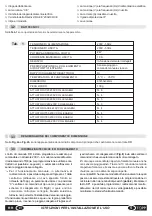
Страница 13: ...trol it is possible to connect the J1 input of the control unit to a deviator key with central 0 position see connection diagram in Fig 9 equipped with deadman switch using the special cable supplied on request by Topp which will control the actuator This solution however does not permit installation of the rain sensor Automatic function follows a predefined logic When it rains 3 3 LIST OF PARTS A...

Страница 14: ...ly on the window a suitable safety warning and or install an acoustic luminous warning signal in the vicinity If the movable part of the window is under 2 5m respect to the floor it would be advisable to use actuators in according with the EN 60335 2 103 directive or shield the dangerous parts with suitable safety In order to assist installers in applying the European regulations and directives re...

Страница 15: ... constantly verify the functional efficiency in time and nominal performance of the actuators the windows where they are installed and the electrical system and when necessary shall have qualified technical personnel perform actions of routine and special maintenance to guarantee proper working conditions and respect of the safety regulations The user before using the motors connected to the power...

Страница 16: ...trol unit is on stand by awaiting a manual or automatic command the green led is on with fixed light and the red led is off When the unit receives a radio signal from a programmed radio control device it converts it into an open or closure command the green led blinks and the red led is off The green led L2 blinks for the duration of the radio signal If the key is released on the transmitter the g...

Страница 17: ...r due to exposure to sunlight or extreme weather dullness of coloring and or deformity of the external casings discoloration opaque spots cracks Demolition of the power unit must be handled in respect of the legislation in force on the subject of environmental safeguards It is therefore necessary to separate the parts of the power unit depending on the type of material 17 EN RR key 2 of the radio ...

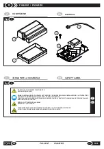
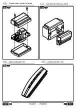
Страница 18: ...ORE LEGGANO E COMPRENDANO IN TUTTE LE SUE PARTI IL MANUALE THE INSTALLER AND USER MUST READ AND UNDERSTAND ALL PARTS OF THIS MANUAL BEFORE INSTALLING AND USING THE ACTUATOR PERICOLO ATTENZIONE ALLE MANI BEWARE OF YOUR HANDS ATTENZIONE MACCHINAAD AVVIAMENTO AUTOMATICO CON COMANDOADISTANZA ATTENTION AUTOMATIC MACHINE WITH REMOTE CONTROL DEVICE IT EN Fig 3 IT TARGA PER LA SICUREZZA EN SAFETY LABEL 3 ...

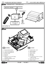
Страница 19: ...ND 1 Actuator 230V input 2 Green led signal 3 Red led signal 4 Radio receiver 5 Dip switch 6 SP1 button 7 J1 input for rain sensor or manual control via cable 8 230V power supply input 9 Radio Antenna EN LEGENDA 1 Ingresso Attuatore 230V 2 Led verde di segnalazione 3 Led rosso di segnalazione 4 Ricevitore radio 5 Dip switch 6 Tasto SP1 7 Ingresso J1per sensore pioggia o pulsante via cavo 8 Ingress...

Страница 20: ...20 FIGURE FIGURES RR IT FIGURE PER L INSTALLAZIONE EN FIGURES FOR INSTALLATION Fig 5 Fig 6 EN RADIOCONTROL TR8 IT RADIOCOMANDO TR8 1 2 3 4 5 6 7 8 Fig 7 ...

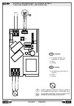
Страница 21: ...ain sensor 1 2 3 4 ON nero black nero black nero black grigio gray grigio gray grigio gray marrone brown marrone brown marrone brown blu blue blu blue blu blue bianco white bianco white bianco white giallo yellow giallo yellow giallo yellow 230V A QUESTO SIMBOLO IDENTIFICA NEGLI SCHEMI DI COLLEGAMENTO ELETTRICO L ATTUATORE TOPP IT THIS SYMBOL IDENTIFIES THE ACTUATOR TOPP SPA IN THE ELECTRICAL CONN...

Страница 22: ...brown marrone brown blu blu blue blue blu blue bianco white bianco white bianco white Giallo yellow Giallo yellow Giallo yellow A QUESTO SIMBOLO IDENTIFICA NEGLI SCHEMI DI COLLEGAMENTO ELETTRICO L ATTUATORE TOPP IT THIS SYMBOL IDENTIFIES THE ACTUATOR TOPP SPA IN THE ELECTRICAL CONNECTION LAYOUTS EN 230V P O C LEGENDA P Pulsante deviatore con posizione 0 centrale O Apre C Chiude IT LEGEND P Deviato...

Страница 23: ......
Страница 24: ...TOPP S r l Società a Socio Unico soggetta a direzione e coordinamento di 2 Plus 3 Holding S p a Via Galvani 59 36066 Sandrigo VI Italia Tel 39 0444 656700 Fax 39 0444 656701 Info topp it www topp it ...

Отзывы: