


21
c
4
c
3
c
2
c
1
c
7
c
6
c
5
c
4
c
3
c
2
c
1
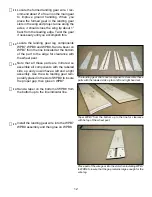
STABILIZER ASSEMBLY
Place the stabilize plans on the work bench
and cover them with waxed paper. Locate
S5 and carefully align it with the plans and
pin it in place.
Locate the two S4 pieces and glue them to
S5, use a straight edge to insure they are
straight.
Stabilizer assembly under way. The straight edge (ruler) is
used to insure that the S4 trailing edge pieces are perfectly
parallel.
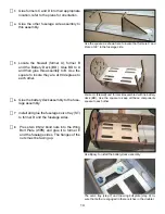
Glue the stabilizer tips S3 to S4.
Glue S2 to S3 and S5.
Glue S1 to S4, S3 and S2.
Install and glue ribs S6 and S7 in the notch-
es provided.
Sand the stabilizer flat and round over the
leading edge and the stabilizer tip. Leave
the trailing edge square as well as the cen-
ter section at the leading edge where it will
engage the fuselage.
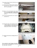
ELEVATOR ASSEMBLY
Place the elevator halves over the plans.
Use a straight edge secured them to the
building board to insure they are straight.
Pin the elevator halves in position.
Locate the 3/32: wire elevator joiner, center
it at the leading edge and apply pressure to
dimple the leading edge.
Remove the elevator halves and drill a
7/64” hole in the center of the stabilizer half
at the location of the dimple.
Marking the leading edge of the elevators for drilling holes
for the wire joiner. Note the straight edge to keep the halves
perfectly parallel.
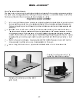
Carve a grove in the center of the stabi-
lizer half from the hole to the inboard end
to receive the wire joiner. Note this can be
done nicely by dragging the drill nit back
and forth along the leading edge. Make it
just deep enough so the joiner is flush with
the surface.
Dragging a drill bit on it’s side makes a great tool for digging
the grove in the leading edge.
Содержание MINI SUPREME
Страница 2: ......
Страница 38: ...Top Notch Products Company PO Box 1051 Goodlettsville TN 37072 Phone 615 866 4327...


