10
❏
❏
15. Once the solder has cooled slide a silicone
clevis keeper over each clevis. Install the pushrod
wire assembly to the aileron servo arm and aileron
control horn.
❏
❏
16. Use the same procedure for the fl ap servo
except you will not center the servo. Instead, make sure
the fl ap is fully closed to the bottom of the wing. Then
position the servo arm so that it is rotated toward the
wing trailing edge. Now you can proceed with making
the pushrod wire assembly.
❏
17. Repeat steps 1-16 for the left wing.
Did You Know?
Did You Know?
The Mitsubishi Zero was a long-range fi ghter aircraft,
manufactured by Mitsubishi Heavy Industries, and
operated by the Imperial Japanese Navy from 1940 to
1945. The A6M was usually referred to by its pilots as
the “Zero-sen”, zero being the last digit of the Imperial
year 2600 (1940) when it entered service with the
Imperial Navy. The offi cial Allied reporting name was
“Zeke”, although the use of the name “Zero” was later
commonly adopted by the Allies as well.
INSTALL THE RETRACTABLE
LANDING GEAR AND
LANDING GEAR DOORS
This airplane was designed to use the Robart Landing
Gear. These instructions show the installation of the
pneumatic landing gear. Robart also produces an
electric version of this landing gear. Part numbers for
both versions are listed on page 5 of the manual. We
have chosen to show the pneumatic installation as it
has a few additional steps to complete the installation.
Both the pneumatic and the electric versions of this
landing gear will work in this airplane.
❏
❏
1. Determine which of the landing gear mounts in
the right wing. Install your gear into the right wing fi rst
so your assembly matches the photos in the manual.
❏
❏
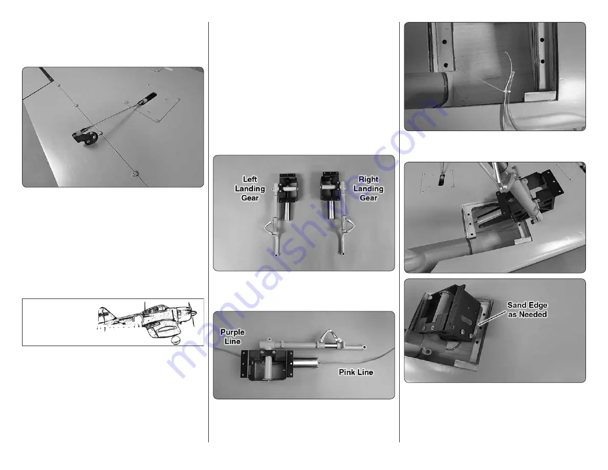
2. Cut the Robart pink and purple airline (not
included in the kit) in half, making two pink and two
purple 30" [762mm] lengths. Install one of the pink and
purple lines onto the fi ttings as shown.
❏
❏
3. Inside of the wheel well there is a string. Tie
the string to the end of the two airlines.
❏
❏
4. Install the gear into the wheel well. It will be a
tight fi t and may require you to sand the edge of the
opening a bit to fi t the landing gear. When installing
the gear into the opening you will fi nd that moving the
landing gear strut to different positions while inserting
it will make it install into the opening easier.
Содержание GIANT SCALE GOLD EDITION ZERO
Страница 39: ...OS GT60 Mounting Pattern Top of Firewall 78 44 mm 66 48 mm...
Страница 40: ......


