

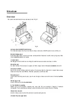


Structure
Overview
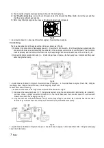
The Injector Cleaner& Tester structure has been shown in Fig.01.
Fig.01
A-Power socket & ON/OFF Switch & Fuse
For introduce AC power into the unit, and there’s a fuse socket, and a ON/OFF switch to turn on/off the unit.
B-Control/display panel
All the data will be shown on this touch screen, and adjustment of parameter could be done by finger tap. Refer
to the
Control Panel
section for details
C-
Control knob
Fast Navigation and control knob, turn left/right to switch between parameters and press to confirm.
D-Fuel filler port
For refill of test fuel. The fuel reservoir capacity is 2100ml, always refer to the
Fuel level indicator
while refill.
E-
Fuel level indicator
Note the fuel level at refilling, and before testing. The fuel level shall be checked at a regular basis, always
make sure the fuel level over MIN line, otherwise, pump faulty could be resulted.
F-Fuel drain port
If the fuel becomes dirty, drain the fuel, pour the fuel through a strainer and refill it back in from the
Fuel filler
port
.
G-Fuel supply hose
Used to introduce fuel to the
Fuel distributor
.
H- Fuel distributor assembly
Different type of fuel distributor assembly may come with the unit according to changes of hardware
configuration. The Fuel distributor assembly is used to distribute fuel into mounted injectors for testing.
I-Return fuel connector
Used for introduce return fuel from the vehicle at on-vehicle-testing function.
J-Sockets for pulse signal cable
Содержание GDI
Страница 1: ...Automotive Fuel Injector Tester PFI GDI GS6...
Страница 16: ......