


through the medium to provide powerful cleaning on objects with complex shapes, cavities and pores, so that the stubborn
carbon deposits can be removed from the injectors.
Procedures
1) Connect the power supply: connect one end of the power cable to the power socket on ultrasonic cleaner and the other
end to power socket.
2) Place the injectors which have gone through surface cleaning in a launder.
3) Add enough injector detergent into ultrasonic cleaner so that the liquid level is about 20mm above the needle valve of
injectors.
4) Plug the injector pulse signal wires to injectors respectively then turn on the power switch of the ultrasonic cleaner.
5) Tap <
Ultrasonic cleaning
> icon on the main screen. Tap the time to set the timer (1~60min, and 10 minutes by default)
then tap the <
Run
> button.
6) When the time is up, Injector Cleaner & Tester will stop automatically.
7) Turn off the power of the ultrasonic cleaner, take the injectors out of the launder and wipe them with a dry soft cloth.
And they are ready for next operation.
Note:
Never operation the ultrasonic cleaner when the tank’s empty, otherwise, damage may be incurred.
Do not dip the pulse signal cables plug and the injector’s body into the detergent.
Uniformity/Spray-ability Test
Uniformity test is to find out if the flow of different injectors meets the requirement or specifications under the same working
condition. This test can reflect the comprehensive influences on the injector caused by electrical nature, bore variation and
clogging. Spray-ability test is to inspect the spraying performance by observing the injectors.
Installing and testing procedures for top-supply injectors
1) Choose the fuel distributor stopper (4) from the coupler box and mount a proper O-ring on it. Remember to apply a little
lubricating grease on the O-ring. Mount the fuel distributor stopper (4) onto the top-supply fuel distributor.
2) Mount the crescent plate (3) and tighten it with a plate bolt (1).
3) Choose a proper adaptor (5) according to the injector type and mount it to the corresponding coupler under the
top-supply fuel distributor.
4) Install the injectors in forward direction (Apply a little lubricating grease on the O-ring.)
5) Install the top-supply fuel distributor and the injector on the fuel distributor supporter with a proper adjustable screw and
knurled nuts, and tighten two riffle screws (black). See Fig. 05.
6) Connect the injector pulse signal wire.
7) Before doing this test, tap <
Drain
> button to drain the test liquid from the measuring tube if there is any.
8) Tap <
Uniformity/Sprayability test
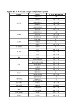
> icon on the control panel, set corresponding parameters (consult the appendix for
pressure setting, consult vehicle manuals for other parameters as needed), and then press <
Run
> button to start the
test.
9) When the test is completed, the equipment will auto stop with the ring of the buzzer.
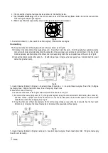
Fig. 05 For fuel top-supply injector
1-Plate bolt; 2-Riffle screw; 3-Crescent plate; 4-Fuel distributor stopper; 5-Adapter for fuel top-supply injector;
6-Injector;7-Knurled nut; 8-Adjustable screw
Installing and testing procedures for side-supply injectors<while parts are available>
1) Choose proper couplers for side-supply injectors (3) and proper O-rings, and mount them together. (Remember to
apply a little lubricating grease.)
Содержание GDI
Страница 1: ...Automotive Fuel Injector Tester PFI GDI GS6...
Страница 16: ......