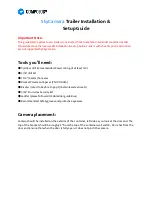
background image

14

Buffer material

Camera Unit

Composite cable

3. When installing the camera, ensure that ceiling is strong enough to withstand the camera load. 

Note:

Be sure to seal and insulate each connection of the cable with waterproof tape.

4. Remove the buffer material for transportation from the camera unit.

Содержание C-CC704 CU

Страница 1: ...etting procedure refer to the setting manual in the manual CD supplied with the unit INSTALLATION MANUAL Thank you for purchasing TOA s Combination Camera Please carefully follow the instructions in t...

Страница 2: ...n speed setting switch No 9 9 6 1 4 Termination switch No 10 9 7 CONNECTIONS 7 1 Composite Cable Specifications 11 7 1 1 Wiring specification 11 7 2 Note on Camera Installation 12 7 3 Camera Control C...

Страница 3: ...o prevent lightning strikes install the unit at least five meters away from a lightning rod and yet within the protective range angle of 45 of the lightning conductor Lightning strikes may cause a fir...

Страница 4: ...ice personnel Do not insert nor drop metallic objects or flammable materials in the ventilation slots of the unit s cover as this may result in fire or electric shock Do not touch the unit during thun...

Страница 5: ...equency energy and if not installed and used in accordance with the instruction manual may cause harmful interference to radio communications Operation of this equipment in a residential area is likel...

Страница 6: ...t life with prolonged unit use under high temperature and high humidity Since the airtightness of unit structure is high enough moisture could get inside the camera causing the inside of the dome cove...

Страница 7: ...d off remotely When cleaning the unit be sure to switch off the power Wipe with a soft dry cloth If it gets very dirty use the soft cloth slightly moistened in neutral cleanser Never use thinner benze...

Страница 8: ...8 Back side of the case Top view of the camera unit 5 NOMENCLATURE Case Camera unit Dome cover Input output connector Power supply connector DIP switch Pipe receptacle cover...

Страница 9: ...ng switch No 9 Check to make sure that this speed is set identical to the communication speed set to the Remote Controller When changing the communication speed change settings for all the cameras and...

Страница 10: ...0 ON 1 2 3 4 5 6 7 8 9 10 ON 1 2 3 4 5 6 7 8 9 10 ON 1 2 3 4 5 6 7 8 9 10 ON 1 2 3 4 5 6 7 8 9 10 ON 1 2 3 4 5 6 7 8 9 10 ON 1 2 3 4 5 6 7 8 9 10 ON 1 2 3 4 5 6 7 8 9 10 ON 1 2 3 4 5 6 7 8 9 10 ON 1 2...

Страница 11: ...posite Cable Specifications Video output cable Power supply cable Camera control cables Alarm input cables Input output connector Power supply connector Input output connector Terminal No Terminal nam...

Страница 12: ...nnect to the next camera s camera control terminal Connect to Remote Controller s camera control terminal Camera control cable GND GND 7 2 Note on Camera Installation Be sure to seal and insulate each...

Страница 13: ...pper side of the case then secure the case to the ceiling Use screws with a nominal diameter of 4 mm and a length of over 25 mm Notes When installing the camera ensure that ceiling is strong enough to...

Страница 14: ...3 When installing the camera ensure that ceiling is strong enough to withstand the camera load Note Be sure to seal and insulate each connection of the cable with waterproof tape 4 Remove the buffer m...

Страница 15: ...over fixing screw accessory Camera unit Dome cover 5 Attach the dome cover to the camera unit 6 Perform DIP switch settings For switch settings refer to p 9 7 Connect the safety wire secured to the ca...

Страница 16: ...ite cable 8 Connect the composite cable connected to the cables extended from the ceiling to the camera unit 9 Secure the camera section camera unit dome cover to the case using the supplied TORX wren...

Страница 17: ...Threads 3 Run the cables through the pipe pull them out from the case opening then secure the case to the ceiling Use screws with a nominal diameter of 4 mm and a length of over 25 mm For the details...

Страница 18: ...ination camera 9 SYSTEM EXAMPLES 9 1 Connection Example to the Digital Video Recorder Note It is possible to use the Combination Cameras in any combination When using the Combination Cameras in combin...

Страница 19: ...50 IRE 0 03 lx 20 IRE Backlight Compensation ON OFF High Sensitivity Function Slow shutter mode 64 times max White Balance ATW AWB Iris Automatic Flicker Reduction Automatic correction Electronic Zoo...

Страница 20: ...screw M4 x 10 3 Composite cable 1 TORX wrench 1 Sealing tape 1 Optional products Wall Mounting Bracket C BC704W Pole Mounting Bracket C BC771PM Flush Ceiling Mounting Bracket C BC704U Pendant adapter...

Отзывы: