


TM 9-1829A, April 1944
98/100
2021-07-07
Chapter 13: Calibrating machine
65. Description
a.
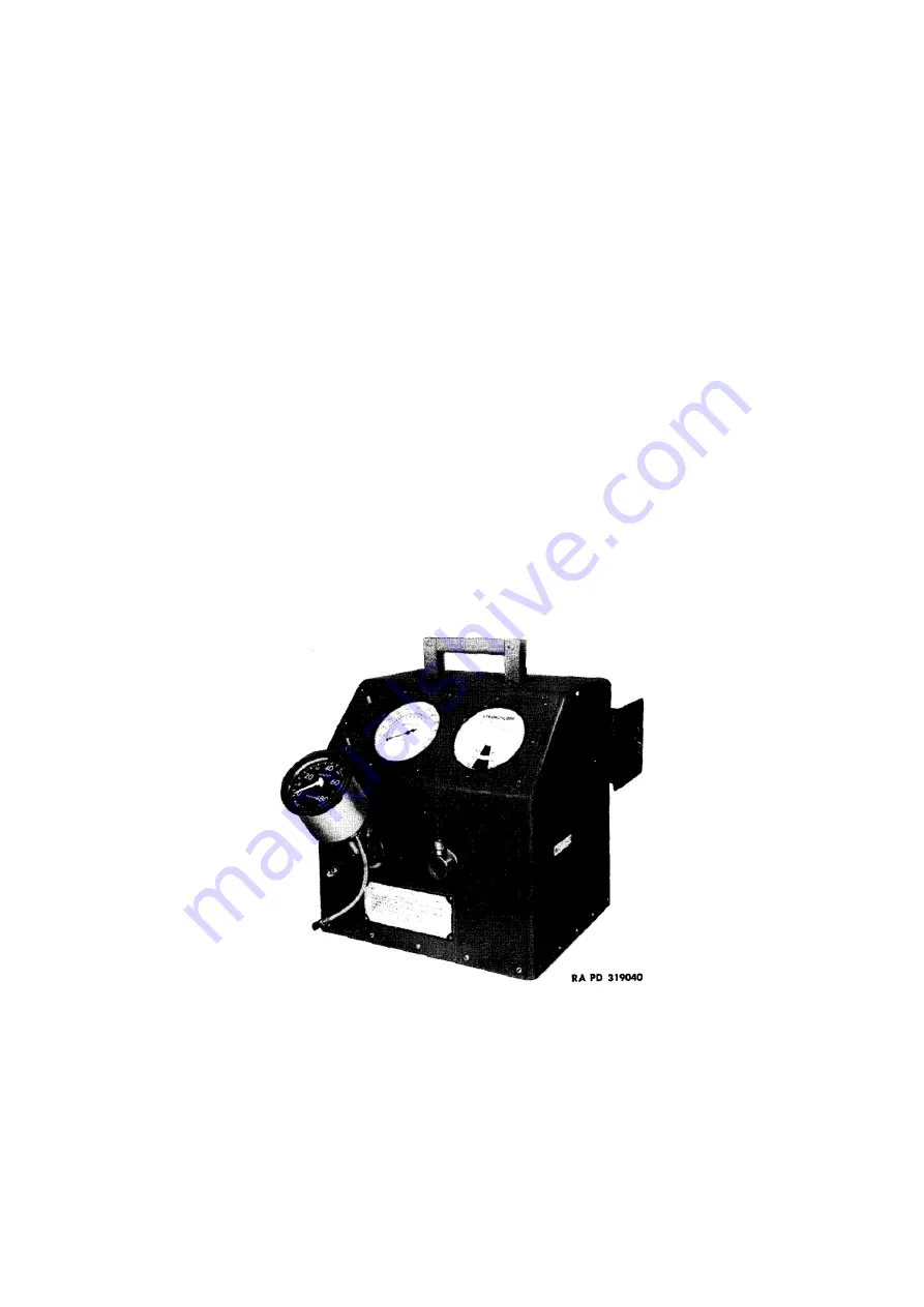
The calibrating machine (T-170645), manufactured by Stewart-Warner Corporation, is supplied with
attachments for testing and calibrating all makes of speedometers and tachometers. Swivel joints (T-176827,
clockwise; T-178704, counterclockwise) allow the operator to hold the instrument being calibrated in the
same position as it would be mounted on the vehicle. Three 72 inch flexible shafts (36,800, 97,800 and
95,000) are provided for connecting the calibrating machine spindles to instruments in vehicles, for testing
speedometers and tachometers without removal from vehicle. The master head on calibrating machine has a
combination face dial reading zero to 120 miles per hour and zero to 5,000 revolutions per minute. Spindle
No. 1 turns 1,000 revolutions per minute when master head indicates 2,000 revolutions per minute and 60
miles per hour. This spindle is therefore used for calibrating practically all speedometers (fig. 155) except
those that indicate 60 miles per hour at 2,000 revolutions per minute shaft speed (such as used on Harley-
Davidson motorcycles). Spindle No. 1 is also used for calibrating all tachometers that indicate twice the
flexible shaft speed (two to one calibration), as the master revolutions per minute scale reading will then agree
with the tachometer being calibrated. Spindle No. 2 turns 2,000 revolutions per. minute when master head
indicates 2,000 revolutions per minute and 60 miles per hour. It is used for tachometers calibrated one to one,
and all other ratios (except two to one). Spindle No. 2 is also used for speedometers that indicate 60 miles per
hour at 2,000 revolutions per minute as mentioned above. In addition to the master head, a stroboscope is
provided for checking master at 30, 60, and 90 miles per hour. Any errors in the master can thus be readily
detected, and it can be repaired as instructed in chapter 6, section II of this manual. The calibrating machine
is powered by a
1
/
8
-hp, 110-volt, 60-cycle AC motor, with variable friction drive. An automatic throwout is
provided to protect this drive when the machine is operated at zero reading on the master head. Ball bearings
are used throughout the mechanism. The speed of the machine is controlled by a wheel at the lower right end
of the case. “ON-OFF” switches for the motor (lower switch) and stroboscope (upper switch) are located to
the left of the master head. Equipped with carrying handle, six-foot electric cord, and drawer with lock (for
small tools). Olive-drab wrinkle enamel finish.
Figure 155: Calibrating machine (T-170645) with speedometer mounted on spindle no. 1 ready for test
66. Operation
a.
Plug electric cord into wall outlet. The standard machine requires 110-volt, 60-cycle alternating current. Turn
motor switch (lower) to “ON” position and allow machine to “warm up” for a few minutes, running at less
than 30 miles per hour. Then turn stroboscope switch (upper) to “ON” position, gradually turn speed control
wheel until dots on stroboscope “stand still” at 30 miles per hour and note master head to make sure it also
reads 30 miles per hour. Also check master at 60 and 90 miles per hour against stroboscope. Then turn
stroboscope switch to “OFF” position. When increasing speed of calibrating machine, always turn control
wheel slowly. Make sure instrument which is to be tested or calibrated is not “bound up”. Select proper swivel
joint and adapter. The regular swivel joint (T-176827) is used with instruments having a clockwise face dial.